Difference between revisions of "Terminology & Concepts"
m ([[{{PAGENAME}}#Equal Loudness Curves|Equal Loudness Curves]]) |
m |
||
| (12 intermediate revisions by the same user not shown) | |||
| Line 5: | Line 5: | ||
http://meta.wikimedia.org/wiki/Help:Template#Composite_pages | http://meta.wikimedia.org/wiki/Help:Template#Composite_pages | ||
| − | Almost all the content is in individual articles that are | + | Almost all the content is in individual articles that are presented here as on very long page. |
To edit any section you need to edit the original page that appears like | To edit any section you need to edit the original page that appears like | ||
| Line 12: | Line 12: | ||
--> | --> | ||
__NOEDITSECTION__ | __NOEDITSECTION__ | ||
| + | <table><tr> | ||
| + | <td valign="top" width="450">__TOC__</td> | ||
| + | <td valign="top"> | ||
| + | This '''extremely long''' page is a composite of many individual pages. I have put them together to make it easier to: | ||
| + | * read all of the major terms and concepts in one place | ||
| + | * use the Find function in your browser if you are looking for a specific phrase (Ctrl-f for PCs or Command-f for Mac) | ||
| + | * print everything all in on page (see menu at left for Printable version) | ||
| + | |||
| + | {{:Different Models}} | ||
| + | |||
| + | {{:Common Terms and Acronyms}} | ||
| − | + | </td> | |
| − | + | </tr></table> | |
| − | |||
| − | |||
== Backline Amplifiers == | == Backline Amplifiers == | ||
| Line 54: | Line 63: | ||
== Localization, Spaciousness and Reverberation == | == Localization, Spaciousness and Reverberation == | ||
{{:Localization Spaciousness Reverberation}} | {{:Localization Spaciousness Reverberation}} | ||
| + | |||
| + | == Microphone Directionality == | ||
| + | {{:Microphone_Directionality}} | ||
== Nulls == | == Nulls == | ||
| Line 63: | Line 75: | ||
== PA == | == PA == | ||
{{:PA}} | {{:PA}} | ||
| + | |||
| + | == Phantom Power == | ||
| + | {{:Phantom Power}} | ||
== Phase (cancellation, interference) == | == Phase (cancellation, interference) == | ||
| Line 68: | Line 83: | ||
== Presets == | == Presets == | ||
| − | {{: | + | Presets are ToneMatch® Presets. |
| + | |||
| + | {{:ToneMatch®}} | ||
| + | |||
| + | See also: [[Presets]] | ||
== Processors == | == Processors == | ||
| Line 79: | Line 98: | ||
{{:Reverberant Field}} | {{:Reverberant Field}} | ||
| − | == | + | == Sound Pressure Level == |
| − | {{: | + | {{:Sound Pressure Level}} |
| + | |||
| + | == Spectral Identification == | ||
| + | Vocabulary for discussing sound. | ||
| + | |||
| + | {{:Spectral Identification}} | ||
| + | |||
| + | |||
| + | == ToneMatch® == | ||
| + | {{:ToneMatch®}} | ||
| + | |||
| + | == Triple System Amplification == | ||
| + | {{:Triple Amplification System}} | ||
| + | |||
| + | |||
| + | == Volume == | ||
| + | {{:Volume}} | ||
---- | ---- | ||
Latest revision as of 15:08, 18 June 2016
Contents
|
This extremely long page is a composite of many individual pages. I have put them together to make it easier to:
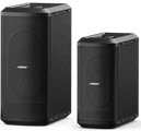
How to Tell the Difference Between Bose Portable PA ModelsThis is how to tell which L1®, S1 Pro, or F1 unit you have.
Compatibility with Other Members of the L1® Family of ProductsCylindrical Radiator®sCylindrical Radiator®s are not interchangeable across modelsSpecifically (and without exception)
T1 ToneMatch® Audio Engine, T4S/T8S ToneMatch® Mixers
PackLite® power amplifier Model A1
B1 Bass Module
B2 Bass Module
Common TermsL1®L1 is often used to refer to one system including the L1 Cylindrical Radiator® loudspeaker, Power Stand, and one or more B1 Bass Modules. "PAS" has never been used by Bose out of respect for another company's trademark.
Classic (L1® Classic)
L1® Model I (L1® Model I)
Distinguishing features include orange labels on the back of the power stand and on the line arrays. Also many of the accessory connectors have been removed on the back panel. See L1® Model I
L1® Model II (L1® Model II)
T1® (T1 ToneMatch® Audio Engine)
A1 (PackLite® power amplifier Model A1)
B1 (B1 Bass Module)
For the L1 Classic and L1 Model I the B1 Bass Module is optional. With the L1 Model 1S and L1 Model II at least one bass module B1 Bass Module or B2 Bass Module is required for the proper operation of the System. See: B1 Bass Module B2 (B2 Bass Module)
For the L1 Classic and L1 Model I the B2 Bass Module is optional. With the L1 Model 1S and L1 Model II at least one B1 Bass Module is required for the proper operation of the System. See: B2 Bass Module L1 Cylindrical Radiator® loudspeakerThis refers to the actual loudspeaker that plugs into the L1 Power Stand. This breaks down into two pieces for transport, but when assembled, functions as a single unit. See: L1 Cylindrical Radiator® loudspeaker
|
||||||||||||||||||||||||||||||||||||||||||||||||||||||||||||||||||||||||||
Backline Amplifiers
The amplifiers that musicians typically have on stage (behind them) to amplify the sound of their instruments. Examples: Guitar amps, Bass amps, Keyboard amps.
Some musicians (Electric Guitarists especially) treat their backline Amplifiers as part of the instrument. For these folks there is just no substitute for that sound. Micing the speaker cabinet and amplifying it through the Bose Personalized Amplification System™ is a completely viable way to let them create the tone and share it with the room.
Comb Filtering
Comb filtering occurs when two identical (or nearly identical) signals, one delayed in time relative to the other, are added. Depending on the delay time, the resulting summed signal can sound hollow or “boingy”, and is usually considered an undesirable sound.. Comb filtering occurs most commonly when signals are combined electronically, such as in a hard disc based recording system, but can also occur acoustically, such as a talker located slightly off axis of two identical microphones spaces inches apart.
(Thanks to Ken-at-Bose for this information).
Critical Distance
The distance from the acoustic centre of the source to the point at which the intensity of the direct sound equals that of the reverberant field . References: Critical Distance SFU.ca
In audio physics, the distance at which the sound pressure level of the direct and the reverberant field are equal. In other words, the point in space where the echo from a sound source is at the same volume (amplitude) as the source. This distance is dependent on the geometry in which the sound waves propagate, as well as the dimensions and shape of the sound source. Wikipedia
See also: L1® vs B1 Bass Module Fall Off with Distance ⇐ Hilmar-at-Bose talks about Critical Distance and the L1®.
See also: Throw Over Distance ⇐ Comparing the drop-off in volume over distance
Crossover
|
The following is based on information that was available when the L1 Classic was in production. This information is equally applicable to the L1 Model I. The L1 Model II crossover is fixed at 200 Hz and does not vary depending on whether or not B1 Bass Modules are attached to the Power Stand. |
Crossover —Definition
- I'm familiar with the term 'crossover,' but not really with its meaning.
Audio crossovers are a class of electronic filters designed specifically for use in audio applications, especially hi-fi. A commonly used dynamic loudspeaker driver is incapable of covering the entire audio spectrum all by itself. Thus, crossovers serve the purpose of splitting the audio signal into separate frequency bands which can be handled by individual loudspeaker drivers optimized for those bands. A combination of multiple drivers each catering to a different frequency band constitutes most hi-fi speaker systems. An audio crossover may also be constructed mechanically and is commonly found in full-range speakers. -- more at Wikipedia
If you play Guitar then you should be able to relate to the frequencies I will mention to describe the crossover idea. You can use the picture of the Keyboard to help if that works better for you. (Lowest notes are at the top). (click the keyboard to see that image in its original context).
Your bottom E string has a fundamental frequency of about 82 Hz. (Cyles per second). That is just a reference for this discussion.
When there is nothing attached to Amp 3 output (where we normally connect the blue B1 cable) the Powerstand does this:
L1 Classic and L1 Model I
- Frequencies above 110 Hz are sent to the L1 Cylindrical Radiator™ This is less of a "crossover" and more of a cutoff just because there's no point sending frequencies to the L1 that it can't reproduce.
- It doesn't mean that if the L1 cutoff is set to 110 Hz, you won't hear anything from the low E string. Our perception of tones is based not only on the fundamental (in the case of the low E at 82 Hz it is lower than 110 Hz), but it is also based on the harmonics we will hear in multiples of the fundamentals (2 x 82, 3 x 82, 4 x 82).
BUT
Add the B1 (with all four conductors working) and the PS1 does this:
- Frequencies above 180 Hz are sent to the L1 (the crossover is moved up).
- Frequencies from 40-180 Hz are sent to the B1 (and some processing (EQ) is applied to the 40-180 Hz range) to optimize things with the design of the B1.
For reference, 40 Hz gets us into the range of the low E string on an Electric Bass (an octive below our low E on an Acoustic Guitar).
Here's a bit more from Hilmar-at-Bose about the really low notes:
24db / ocatve
The crossover in the power stand is a pretty steep one, 24dB/octave. So an octave above crossover, the B1's are 24dB down and below crossover the L1's are 24dB down. They get out of each other's way pretty quickly. — Cliff-at-Bose [1]
More Bass Talk
Hilmar-at-Bose explained in More Bass Talk
Crossover
If there is no B1 and nothing connected to the Bass Line Out. The L1 sees frequencies from 110Hz up. Feeding it anything lower, doesn’t make sense, since it couldn’t produce any acoustic output and if would rip the drivers to shreds.
In any other case the L1 sees signals only from 180Hz up. There is no other variation in frequency or gain for the L1 no matter what else happens
Bass Line Out and B1 behavior
This is based on the design goal that “You should always sound the same; no matter how much Bass stuff is attached” I can try to explain my view of why this is a good design goal (of which you may disagree) but let’s look at the actual behavior first.
Without Bass Line out
1xB1: 40Hz-180Hz, B1 specific EQ, some nominal gain that we call 0dB 2xB1: 40Hz-180Hz, B1 specific EQ, -6dB as compared to nominal
With Bass Line Out
0xB1: 40-180 Hz, flat, roughly the same gain as 2 B1 1xB1: 40Hz-180Hz, B1 specific EQ, -6dB as compared to nominal 2xB1: 40Hz-180Hz, B1 specific EQ, -12dB as compared to nominal
What this complex behavior does is the following. No matter if you attach 1, 2, or 4 B1s, you will get pretty much the same balance between all combined B1s and the L1s. It’s a little off for 3, 5, 6, 7 & 8 B1s, but still reasonably close.
Frequency content of an acoustic guitar
Oldghm, you did some really interesting experiments there. However, you have to be really careful when using an RTA. You can feed these things a pure sine wave at 80 Hz and by turning it up make the 63 Hz and even the 40Hz LED light up. They will be lower than the 80 Hz LED, but still come on. That does NOT mean, that the sine wave contains any other frequency than 80 Hz (it certainly doesn’t). It only means that the RTA has a pretty limited frequency resolution. The 63 Hz LED will respond best to 63 Hz signal but it’s in no way “blind” to 80 Hz signal. Thus being said, the actual frequency content is not easy to determine. All sounds that have a pitch are certainly constraint to 80 Hz and up (in standard tuning) and there isn’t actually too much energy at the fundamental. However, the “non-pitched” sounds like a hard string attack or whacking the top with your hand can very well have lower frequencies. Unfortunately, I don’t have any hard data on that, but we will measure that at some point.
Equal loudness curves
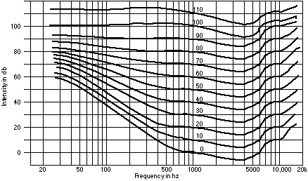
Here is the bunch http://hyperphysics.phy-astr.gsu.edu/hbase/sound/eqloud.html These curves tell us two things: First, the same physical sound energy produces different perceived loudness depending on frequency. You can turn that around into “The physical sound energy required to produce the same perceived loudness varies with frequency”. Second, this frequency dependency is a function of overall level.
The first statement is not particularly bothersome. Your auditory system is well calibrated to that. A voice sounds normal because it sounds like what you are used to, not because it has “constant sound energy” or “constant perceived loudness” with frequency.
The second statement is much more trouble. It basically says that if you amplify an acoustic source (even if you do it perfectly), the perceived spectral balance will change. This is a well-known effect, and most of our home entertainment systems have actually and “automatic loudness compensation” that changes the system voicing with overall level. We actually contemplated adding this to the Personalized Amplification System™ but after some soul searching we thought it would be too intrusive on the musician. The main corrections are at very low levels, and in most practical live music settings, the effect is pretty minor. As a rule-of-thumb guideline, turn the bass up a notch as you turn the volume down.
Crossover with Line Out
- Can I add a Bose bass module like a B1 Bass Module or B2 Bass Module to an L1 Compact or S1 Pro System
- The Line Out from the L1 Compact and S1 Pro System is full range. The B1 Bass Module and B2 Bass Module are designed to work with a signal from 40 Hz to 200 Hz, and preferably with an EQ curve set in the L1 Model 1S or L1 Model II Power Stand.
If you add a PackLite® power amplifier model A1 and B1 Bass Module or B2 Bass Module to an L1 Compact or S1 Pro System you will need a crossover between the Line Out and the PackLite® power amplifier model A1.
Check out these discussions in the community.
The Compact and the B2, via the A1 and the Rolls SX21
- ↑ Cliff-at-Bose Phasing on the Personalized Amplification System
DI (box)
Use a DI when you want to connect two devices and you have any of these issues:
- impedance mismatch
- line level mismatch
- differences in wiring or connectors (e.g. Balanced XLR to Unbalanced 1/4" Tip-Sleeve)
- noise - especially "hum" (Ground Loop)
A DI unit or DI box is an electronic device designed for connecting a piece of equipment with an electronic audio output to a standard microphone or line level input. It performs both level and impedance matching to minimise both noise and distortion. DI is variously claimed to stand for direct input, direct injection or direct interface. DI units are extensively used with professional and semi-professional PA systems and in sound recording studios. -- Wikipedia
You will also see the term DI used to refer to devices used to modify the tone as well as other properties of a signal. This is often in the context of Acoustic Guitar and Electric Bass. In the picture above the first two are passive DIs used for solving problems. The others are all sold as DIs that also shape the sound.
More info about DI's
- http://whirlwindusa.com/support/tech-articles/direct-box-can-be-di-spensible/
- http://www.leonaudio.com.au/active.htm
This is an excerpt - follow the link above for the full story.
What's in a D.I. Box?
D.I. Boxes are constructed using one of two common techniques.
- The first type uses electronic circuitry and are known as active D.I. Boxes. They require either Phantom Power or a battery supply.
- The second type uses an audio transformer and are known as either transformer or passive D.I. Boxes. They require no power supply.
A D.I. box is required to perform three separate basic tasks:-
1. Impedance Conversion. 2. Unbalanced to balanced conversion. 3. Earth isolation.
Impedance Conversion
The medium or high impedance of a signal source is converted to a low impedance suitable for feeding down a long multicore to a mixing desk’s microphone input. A low impedance enables long cable runs, with very little quality loss, and also low susceptibility to external electrical interference which can cause hum and buzzes.
A D.I. box should provide a high input impedance for connection to a signal source, and a low output impedance for connection to the microphone input of a mixing desk.
Unbalanced To Balanced Conversion
The unbalanced (2 conductor) wiring of a signal source is converted to the balanced (3 conductor) wiring of a mixing desk’s microphone input. A balanced cable provides good rejection of electrical interference, while an unbalanced cable does not. Active D.I. Boxes are potentially capable of providing excellent unbalanced to balanced conversion, but due to cost restrictions, most are poor performers in this area. D.I. Boxes that incorporate transformers provide excellent unbalanced to balanced conversion.
Earth Isolation
A D.I. Box provides isolation between the earth wiring of a signal source (e.g. musical instrument) and the sound system to which it is being connected. This prevents earth loops from occuring. An earth loop occurs when a device, such as a keyboard, is connected to the mains earth via more than one path. The first path is via the instrument’s own power cable to the mains earth. The second path is via the interconnecting audio cable to the sound system, then via the sound system’s power cable to the main’s earth. Any resultant circulating earth current is amplified and is heard as a hum or buzz. These unwanted earth currents are usually induced from nearby power and lighting cables.
Dual Mono
Introduction
This article pertains to Dual Mono with all L1 systems.
L1 Systems
The L1 systems have extremely wide horizontal dispersion. As a result, running multiple L1 systems in the same sound field may result in overlap. The comments below are applicable in that context.
Non-L1 Systems
The F1 Model 812 Flexible Array Loudspeaker and S1 Pro System systems have narrower horizontal dispersion. If you space those systems apart or aim them to avoid overlap, this article is not applicable.
Dual Mono
This is amplifying the same sound source through two separate loudspeakers.
Hilmar-at-Bose wrote:
- Dual mono (with the L1 systems) is usually not a good idea, if you have more than one performer. With more than one performer/source it's in my opinion always preferable to separate the sources (i.e. one source per L1). The spatial separation and precise localization help more with clarity much more than the added gain.
- For a single performer/single source, it's not quite so clear cut. One will be more accurate (i.e. sound is clearly located at the performer's position, more consistent spectrum) and two will sound wider and more spacious. In the end, that is an artistic decision, depending on which one is closer to your artistic intent.
- -- Source Dual mono is usually not a good idea
Gain Before Feedback
To optimize gain before feedback, each microphone should be heard through only one L1 .
Feedback occurs when the sound from the loudspeaker (or loudspeakers if a microphone is connected to more than one) is louder at the microphone than the sound of the voice. As you increase the number of loudspeakers a microphone is connected to (e.g., dual mono), you increase the possible paths for feedback and lower the gain before feedback.
Benefits of Two L1 Systems
- Introduction
- This discussion pertains to using two L1 systems with the same sound source (Dual Mono). For a discussion about stereo see Stereo / Mono / Distributed Systems
- What is the benefit of using two L1 systems over one?
- You will get more coverage (based on the distance between the L1 systems) and an increase in loudness (but not double the loudness)[1] .
- How much more coverage will I get?
- The increased coverage will be the result of the distance between the two systems. For example, if you place them twenty feet apart in the horizontal plane, you will get twenty feet more coverage from side to side. You will also increase the overall sound level by +3 dB. Your projection straight ahead may improve but that is harder to predict as the distances increases.
- How much gain do you get when you run two L1 systems with the same source?
- Short answer: +3 dB in practice
- +6 dB in theory
The most you can ever get from putting two sources fed by the same signal together is +6 dB. The reason?
- Sound waves add in space through the principle of superposition. If the waves from two sources perfectly add, you get twice the amplitude, which is +6 dB.
- To get the full +6 dB the two sources have to be spaced very closely together relative to a wavelength of sound. at 50 Hz, where the wavelength of sound is about 20' (about 7 meters) that's pretty easy to do. Massing your bass modules is done for this reason -- to get the 6 dB per doubling of bass module systems. But at 1,000 Hz, where the wavelengths are 12 inches (about 30 cm) you just can't do get L1 speakers close enough. As a result, you get something less than 6 dB because at some angles instead of the sound waves constructively adding they will destructively cancel (one will be partly or completely out of phase with the other).
- +3 dB in practice
Once you separate the sources by several or more wavelengths, the summations and cancellations are so numerous and so complex that we say the two sources are essentially uncorrelated (not strictly true, but for the purposes of this argument, a very close approximation.) When two sources are uncorrelated the only thing you can count on is that the total amount of acoustic power going into the room will be doubled. Doubling the power is +3 dB.
- Is +3 dB twice as loud?
- No
- Doubling the power (+3 dB)is not twice as loud.
- A non-exact rule-of-thumb is that every 10 dB increase is a doubling of perceived loudness. [1]
- Takeaways
- Put bass modules together if you can because they'll give you an honest 6 dB per doubling of bass modules/
- If you are sending a mono or stereo signal to spaced L1 systems, try to space them 20 feet (7 meters) or more if you can because this will minimize any audible cancellations.
Two L1 Systems Overlapping
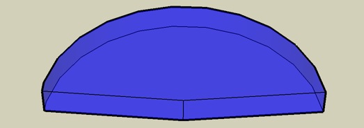
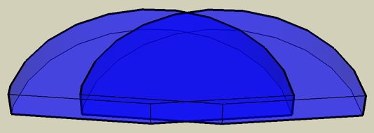
Here are some sketches for discussion purposes. The sound field does not stop abruptly, as might be interpreted by viewing these diagrams. It should continue, fading off gradually, well beyond what is shown here.
These are extremely conservative, and your real-life performance will exceed what is suggested here. We are looking at the relative performance between one L1®. and two.
The view is from behind the wall behind the L1 systems.
Single L1® mono
Two L1®s twenty feet apart — Dual Mono
The darker blue area represents the area where the two sound fields overlap.
Notes:
- Running two L1®s does not project farther forward than one.
- Dual Mono is not recommended.
When you run stereo instead of dual-mono the stereo "sweet-spot" will be extremely wide. You don't have to be between the loudspeakers to hear both Left and Right channels.
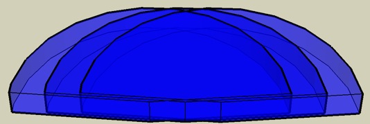
Two L1®s with the original single L1®s field superimposed
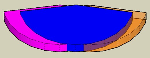
The dark blue area shows the sound field of the original L1™. The lighter area shows the extra coverage you get by having two L1™s 20 feet apart as compared to a single L1™
The extra coverage you get with two L1®s spaced 20 feet apart, is about 10 feet on either side of the sound field of a single L1®s.
- The view from the other side[/b]
(Still very conservative projections)
Blue is the coverage with one L1™. Purple and Orange is the extra coverage that you might get with two L1™s 20 feet apart.
Note: The sound field does not stop abruptly, as might be interpreted by viewing these diagrams. It should continue, fading off gradually, well beyond what is shown here. The purpose of these diagrams is to consider the relative advantages of having two L1®s in dual mono mode compared to a single L1®.
Multiple Source Interference
Phase (cancellation, interference)
Minimum Distance Running Two L1®s in Dual Mono
Phase cancellation can be an issue if you are running Dual Mono (two L1®s from the same mono source). This can be an issue when two or more L1®s are fed the same signal.
The minimum recommended distance for two L1®s running the same signal is 20-50 feet.
Only when fed the same signal, "Interference between line arrays would be more severe [than for non-line-array speakers]. In fact, the current Bose design rules for installing MA12 line arrays recommend ... a spacing between line arrays of between 6 and 15 meters! (20-50 feet)" The same applies to the L1. - Chris-at-Bose [2] (Clarifications added by the author of the quote.)
Note: During a conversation with Chris-at-Bose, he confirmed that the recommendations above are the same for the L1 Model II. ST 15:13, 30 August 2007 (GMT-7)
Theoretical Discussion
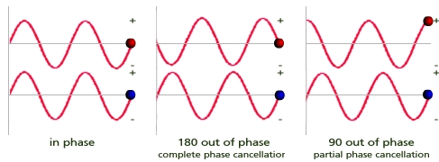
Running two inputs 180° out-of-phase puts the peaks and valleys of the sine wave so that they null each other out when summed (see the middle picture below). This has a tendency to cancel out both inputs, and is quite pronounced in the "far" field, but negligible in the "near" field. Normally phase cancellation is undesirable, but when you know what you want (and in this case, what you don't want) then you do it deliberately.
Phase cancellation occurs when two signals of the same frequency are out of phase with each other resulting in either a boost or cut in the overall level of the combined signal.
-- Phase at the Zen Audio Project
If you are suffering from some or all of these, you could be experiencing Phase Interference
- "Hot" and "cold" spots in the audience area
- Tonal coloration
- Poor speech intelligibility
- Lack of music clarity
- Poor gain-before-feedback
- Poor imaging
See: There is an interesting visual presentation of how phase cancellation occurs with two sound sources.
Practical Realities of Phase Interference
See: Phase
Related reading
- Can I Use It as a PA? (Cliff-at-Bose talks about Dual Mono)
- Live or PreRecorded / Stereo and *-Mono Chris Ickler's report on listening tests with four L1®s and multiple B1 Bass modules.
- Stereo / Mono / Distributed Systems Ken-at-Bose
Equal Loudness Curves
In many discussions on the Bose® Pro Portable PA Community you will see references to Equal Loudness Curves (Contours). For the performing musician, this means that what you hear at relatively low levels may differ significantly when you turn up the volume. The difference will be more than volume, it will be in the spectral balance (your tone) of what you hear.
Specifically, if you create your tone for voice or instrument at low levels, when you turn it up for performance what you will hear will be louder but also significantly different with respect to the tone.
Here is an excerpt from Wikipedia
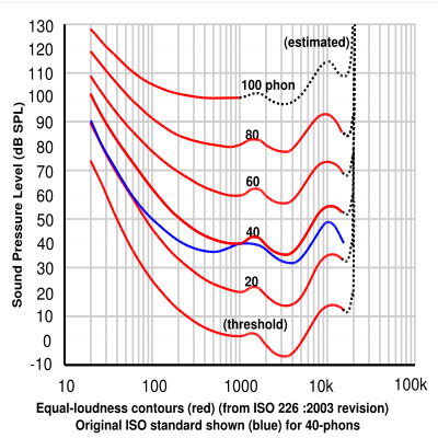
An equal-loudness contour is a measure of sound pressure (dB SPL), over the frequency spectrum, for which a listener perceives a constant loudness when presented with pure steady tones. The unit of measurement for loudness levels is the phon, and is arrived at by reference to equal-loudness contours. By definition two sine waves, of differing frequencies, are said to have equal-loudness level measured in phons if they appear equally loud to the average young person without significant hearing impairment.
Equal-loudness contours are often referred to as 'Fletcher-Munson' curves, after the earliest experimenters, but this is now incorrect, the definitive curves being those defined in the international standard ISO 226:2003 which are based on a review of several modern determinations made in various countries.
Experimental determination
The human auditory system is sensitive to frequencies from 20 Hz to a maximum of around 20,000 Hz, although the hearing range decreases with age. Within this range, the human ear is most sensitive between 1 and 5 kHz, largely due to the resonance of the ear canal and the transfer function of the ossicles of the middle ear.
Equal-loudness contours were first measured by Fletcher and Munson using headphones (1933). In their study, listeners were presented with pure tones at various frequencies and over 10 dB increments in stimulus intensity. For each frequency and intensity, the listener was also presented with a reference tone at 1000 Hz. The reference tone was adjusted until it was perceived to be of the same loudness as the test tone. Loudness, being a psychological quantity, is difficult to measure, so Fletcher and Munson averaged their results over many test subjects to derive reasonable averages. The lowest equal-loudness contour represents the quietest audible tone and is also known as the absolute threshold of hearing. The highest contour is the threshold of pain.
A new experimental determination was made by Robinson and Dadson (1956) which was believed to be more accurate, and this became the basis for a standard (ISO 226) which was considered definitive until 2003, when the standard was revised on the basis of recent assessments by research groups worldwide.
Recent revision aimed at more precise determination - ISO 226:2003
Because of perceived discrepancies between early and more recent determinations, the International Organization for Standardization (ISO) recently revised its standard curves as defined in ISO 226, in response to the recommendations of a study coordinated by the Research Institute of Electrical Communication, Tohoku University, Japan. The study produced new curves by combining the results of several studies, by researchers in Japan, Germany, Denmark, UK, and USA. (Japan was the greatest contributor with about 40% of the data.) This has resulted in the recent acceptance of a new set of curves standardized as ISO 226:2003. The report comments on the surprisingly large differences, and the fact that the original Fletcher-Munson contours are in better agreement with recent results than the Robinson-Dadson, which appear to differ by as much as 10–15 dB especially in the low-frequency region, for reasons that are not explained.[1]
--- Read the whole article: Equal-loudness contour, in Wikipedia
Earlier Notes
"You will see lots of references to equal loudness curves or equal loudness contours- these are based on the work of Fletcher and Munson at Bell labs in the 30s, or perhaps refinements made more recently by Robinson and Dadson. These were made by asking people to judge when pure tones of two different frequencies were the same loudness. This is a very difficult judgement to make, and the curves are the average results from many subjects, so they should be considered general indicators rather than a prescription as to what a single individual might hear" - Numbers and Initials of Acoustics
See also:
http://www.sfu.ca/sonic-studio/handbook/Equal_Loudness_Contours.html
http://hyperphysics.phy-astr.gsu.edu/hbase/sound/eqloud.html
Preset Version 2.0 #57 - the description of Version 2 Preset #57 makes reference to Equal Loudness Curves
Fletcher Munson Curves
See Equal Loudness Curves above
Gain Before Feedback
Gain before feedback refers to the maximum sound pressure level that can be attained before the sound from a speaker enters the microphone and is amplified a second time, creating a loop that only builds on itself: feedback.
An often not very scientific measure of how loud a sound reinforcement system can be turned up before any open microphone(s) will feed back. The point at which feedback occurs is effected by numerous variables, including atmospheric conditions (temperature, humidity, etc.) so it's not something that anyone considers an objective measure of performance. Instead the phrase is used to state relative differences: "By adjusting the EQ I was able to get 'more' gain before feedback." -- Sweetwater
See also Microphone Feedback
Headroom
"Headroom, Max Headroom"
"Headroom is a term used in signal processing (audio, data, etc) to refer to the maximum allowable signal level before compression or distortion."
-- more at wikipedia
"The difference between nominal operating level and peak clipping in an audio system. For example, a mixer operating with a nominal line level of +4dBu and a maximum output level of +22dBu has 18dB of headroom. Plenty of room for surprise peaks."
Source: Mackie ProSound Mixing and Recording Glossary
Having said all that, our Bose Systems if set-up correctly, don't tend to distort as they get louder.
What does tend to happen is, beyond a certain point - they just don't get any louder. That point is well beyond what you would want to endure by the way.
BUT
There are signal peaks - a Drum hit for example that can and maybe should be a lot louder. If the System has lots of headroom, it will be able to accommodate that.
I really do picture our tall friend in the picture above, riding in a vehicle. If the vehicle goes over a quick rise in the road, our buddy may bump his head on the roof of the vehicle. If there is plenty of head room, he won't.
Strange little similes aside, if a system (any system) doesn't distort as it exceeds its capabilities, then it may be difficult to tell (especially with ear-fatigue), just how loud you are running, or that you are just too loud. Some people (not most) get to that point and start experiencing the sense that no matter what they do, the System doesn't get louder, or respond to transient peaks. That's being out of headroom.
ST[1]
Inverse Square Law
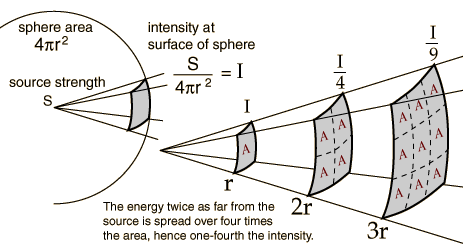
Doubling the distance drops the intensity by about 6 dB and that 10 times the distance drops the intensity by 20 dB.
See The Inverse Square Law Problem
- ↑ ST talks about Headroom in the Bose Musicians Community Message Boards
Localization, Spaciousness and Reverberation
|
This article is an editorial and expresses the opinion and experience of Hilmar-at-Bose the author. Please post comments in the discussion page.
|
Originally posted by Hilmar-at-Bose
[1]
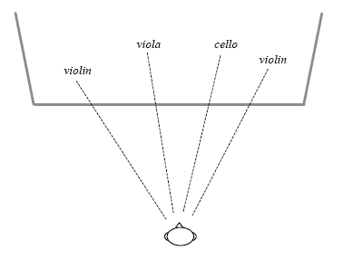
There may be some confusion about “localization” and “spaciousness”. Both are perceptual attributes, which have been intensively studied especially in the context of concert hall acoustics.
"Localization" refers to your ability to detect the direction of a specific sound source. Let’s say you have your eyes closed but you can immediately tell where the guitar is (as opposed to the bass or the violin).
"Spaciousness" refers to the perceived size of the sound source and how much you feel enveloped with sound. Most researchers believe that a “good” concert hall provides both: accurate and easy localization and a sufficient amount of spaciousness.
The main contributing factors for spaciousness are “early lateral reflections”. These are reflections from the sidewalls. Reflections from the side help quite a bit with creating a sense of space and envelopment. Reflection from the floor and ceiling are less desirable since they don’t enhance spaciousness but can negatively impact clarity and spectral balance. There are very interesting physiological reasons of why lateral reflections are perceived so much differently than vertical ones. I could drone on for hours on this topic, but I’ll save that for later. Anyway, it’s not too much of a surprise that most renowned concert halls (e.g. Musikvereinssaal in Vienna, Concertgebow in Amsterdam, or Boston Symphony Hall) have a “shoebox” shape that is long, narrow and tall. This shape provides good lateral reflections pretty much everywhere in the audience. Ironically, it’s not very popular with architects since the sight lines are terrible. Visually oriented architects prefer the “shell” shape, which provides great viewing but (unfortunately) no lateral reflections whatsoever. But I’m digressing again… The L1 does (in my humble opinion) the best thing. It radiates very wide horizontally but very little much towards the ceiling. Thus it provides enough energy for lateral reflections but keeps interfering ceiling reflections at bay. Since it’s a single source, it provides very easy and accurate localization, but in most venues the image will also be pleasantly spacious. That’s at least my own experience. - read it in context[1]
Originally posted by Ken-at-Bose [2] (later in the same discussion):
What we perceive as "reverberance" is caused physically almost entirely by the persistence in time of an acoustic event.
Spaciousness -- the feeling of envelopment and room size is different.
Localization -- where we perceive the sound to be coming from -- is different again.
Localization is almost entirely determined by the direction of the first arrival of sound (almost always the direct sound from the speaker in this case) and thus is almost entirely immune from the effects of reflections. Spaciousness is heavily determined by lateral reflections, which are produced in relative abundance by the L1 because it's so wide in its pattern.
High reverberance is caused by lots of reflections in rooms with little absorption. The L1 is particularly good at NOT producing as much reverberance because it sends little sound to the upper walls and ceiling where many detrimental reflections originate and are perpetuated.
Cocktail Party Effect
The following incorporates two excerpts from "Applying the Benefits of Unamplified Acoustic Music to Performances with Amplification" - pages 11 and 51[3]
Unamplified performances
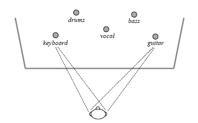
- In an unamplified musical performance, a rich and diverse sound field is created by the arrangement in space of the players and their instruments. Musicians and members of the audience hear the sound of each instrument coming from a different direction, and this direction corresponds naturally to what they see.
- In unamplified performances, regardless of where the listener is located, sound is heard coming from the directions of the individual instruments – directions that furthermore correspond to what is seen.
- The perceptual benefit of having sound from sources in a multi-source environment come from different directions has been extensively studied in the field of psychoacoustics and is known there as the cocktail party effect.2 Other studies show the significant benefit that comes from being able to see and hear a source at the same time, a benefit of special importance in a multi-source environment.3
Fundamental advantages of the new approach
- The advantages of the approach based on the Cylindrical Radiator™ loudspeaker are comprehensive because both the primary and secondary problems characteristic of the triple-system approach are addressed.
- 1. Full use of the property of hearing known as the cocktail party effect
- In the audience and on stage, regardless of location, the sound of each instrument or voice comes from a different direction. Thus the full spatial richness present in an unamplified performance is achieved. The full benefit of the cocktail party effect – the ability to pick out and appreciate individual instruments and voices because they are coming from different directions – is enjoyed by musicians and members of the audience.
- In the approach using Cylindrical Radiator loudspeakers described here, the listener hears sound from the locations of each of the individual instruments, as in an unamplified performance.
Microphone Directionality
There are two basic types of microphone — omnidirectional and unidirectional[1].
Omnidirectional Microphone
Omnidirectional mic. It is sensitive to sounds from all directions.
Best to use when more room ambiance is the goal. Direct and ambient sound can be adjusted by moving the mic closer to or further from the sound source.
Unidirectional Microphone
Unidirectional microphones are sensitive to sound coming from only one direction. Examples:
- a vocalist singing directly on axis directly into the microphone
- a guitar amplifier with the microphone aimed directly at the speaker cone
Cardioid
The most common type of unidirectional microphone is called a “cardioid” because its pickup pattern is heart-shaped. It picks up most sound from the front of the microphone and some from the sides.
Although you will get better gain-before-feedback from a cardioid microphone than an omnidirectional microphone, you will get better gain-before-feedback from a supercardioid or hypercardioid microphone (see next section).
Examples of common cardioid microphones (good to great microphones but not necessarily the best for gain-before-feedback with Bose L1 systems)
- Sennheiser e 835, e 935, MD 935
- Shure SM 58, SM 57, Beta 87C
Supercardioid / Hypercardioid
Supercardioid or hypercardioid microphones offer even greater sound isolation through narrower pickup patterns.
Examples of common supercardioid/hypercardioid microphones
- Audix OM 5, OM 3b, OM 6, OM 7, VX 5
- EV N/D 767A
- Neumann KMS 105
- Sennheiser e 845, e 865, e 945, e 965, MD 441, MD 945,
- Shure Beta 58A, Beta 87A
Nulls
Nulls
Dead spots or areas of a room where there is a significant drop in volume.
When your sound is hollow, diffuse, and thin, you may be experiencing nulls or comb filtering. This is usually the result of a single sound source being amplified through several loudspeakers.
This is a stub.
Out of Phase (for Drum mics)
|
Here are several ways to connect your L1 Classic or L1 Model I to
|
Presets
You will want to try the Kick Drum Presets
- 70 Kick Drum
- 71 Kick Drum, Audix D6
- 72 Kick Drum, AKG D112
- 73 Kick Drum, Sennheiser 601
- 74 Kick Drum, Shure Beta 52a
- 75 Generic Overhead
- 76 Drum Overhead, Differential SM57
- 77 Drum Overhead, Differential Electret
- 00 Flat when you are using a mixer
More Bass for the Kick Drum
If you want to add more low end consider getting a PackLite® power amplifier model A1. You definitely want to read B1 Bass Module/Positioning.
Out-or-Phase Overheads and Kick Drum
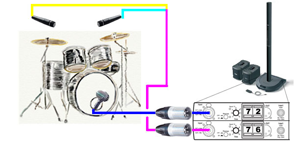
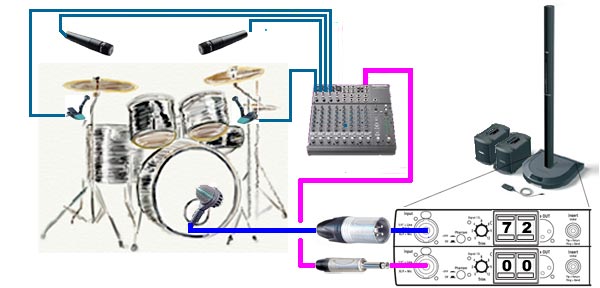
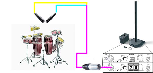
This depicts using two Shure SM57 microphones wired Out-of-Phase. This allows you to have two microphones "overhead" taking only one Channel, leaving another Channel free for the Kick Drum.
- These are not "overheads" but 57's placed below the cymbals and above the top heads of a small kit. The mics are wired out of phase, basically 2 and 3 reversed on an XLR. There's lots written about this on our forum. But the basic idea is that the pair will cancel onstage bass but pick up local instruments on the kit, in an effort to reduce rebroadcasting onstage bass from the drum mics. This way we get a stronger signal than typical overheads and cleaner bass onstage. To "mix" these, just move the mics closer to the instrument you want to emphasize. Typical setup is on either side of the snare facing the snare. Snare is everywhere and there is no need to put a mic directly on it. It's actually pretty easy to set up and adjust, moving the mics around for a good kit mix. With 3 mics and only 2 inputs on the PS1, we get a really nice amplified sound for our shows. I listened to the output of the pair recently (multitrack recordings of a recent show) and the cancelling thing really works great. Give it a try. -- see Out-of-Phase for complete notes.
Using a Mixer
If you want to have more than two or three microphones for Drums, then you can use a mixer for a submix running to one Channel on your Power Stand. Use another Channel (1 or 2) free for the Kick Drum so you can use a Preset. Although it is not shown here, you could run the mixer to Channels 3 or 4. This would leave you with Channel open for a Vocal microphone.
Electronic (V-Drums)
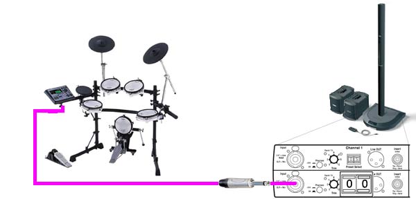
This is as simple as it gets. Your Drum Module controls all the sound and you take the output to one Channel on your L1™. There is no particular advantage to splitting the out the Kick Drum.
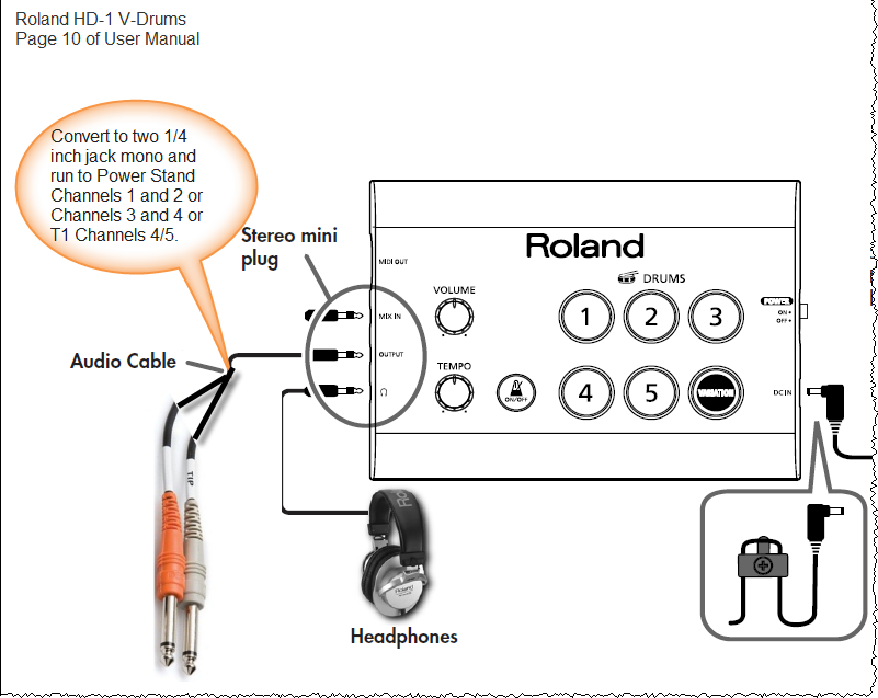
Roland HD-1
Adapted from Roland HD-1 User Manual
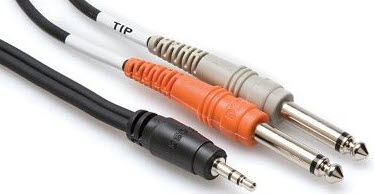
Use a cable like this:
Source: Amazon Hosa CMP159
Percussion with Out-of-Phase Overheads
We are using the same approach for Out-of-Phase microphones as we discussed above.
Out-of-Phase Overheads
Originally posted by Cliff-at-Bose: in Out of Phase Overheads [2]
These are not "overheads" but 57's placed below the cymbals and above the top heads of a small kit. The mics are wired out of phase, basically 2 and 3 reversed on an XLR. There's lots written about this on our forum. But the basic idea is that the pair will cancel onstage bass but pick up local instruments on the kit, in an effort to reduce rebroadcasting onstage bass from the drum mics. This way we get a stronger signal than typical overheads and cleaner bass onstage. To "mix" these, just move the mics closer to the instrument you want to emphasize. Typical setup is on either side of the snare facing the snare. Snare is everywhere and there is no need to put a mic directly on it. It's actually pretty easy to set up and adjust, moving the mics around for a good kit mix. With 3 mics and only 2 inputs on the PS1, we get a really nice amplified sound for our shows. I listened to the output of the pair recently (multitrack recordings of a recent show) and the cancelling thing really works great. Give it a try.
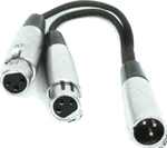
Hilmar-at-Bose talks about Wiring Two SM57s with a Y cord [3]
Here's the nerds view.
Wiring the the two mics out of phase creates essentially a "dipole". Everything that is in the middle (i.e. equal distance) between the two microphones will get equally but out-of-phase so it cancels when the two microphone signals are summed together. In essence it creates a "blind spot" for the microphones for whatever is right in the middle plane. For the drums, that's mainly the kick (as Larry pointed out) and also the drummer (when he/she is hemming and hawing, squeaking with the chair, yelling about or in general having a grand old time).
Another nice trick is to place the L1 that gets the mic signal somewhere in the middle plane of the microphones. This drastically reduces potential for feedback and unwanted regeneration. Sound sources that are significantly closer to any one of the microphones are not much affected by the whole procedure.
the original discussion ← is highly recommended.
Sources for the Cables
Hilmar-at-Bose talks about buying an out-of-phase adapter.[4]
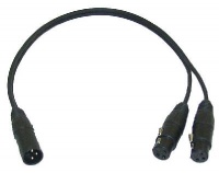
The Y-adapters are pretty rare, I don't think you can buy them on line. You can buy an ordinary 2-female/1-male XLR Y adapter like YMFF type
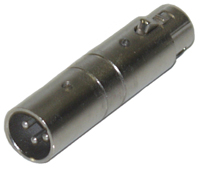
and put an XLR phase inverter on one of the female ends.
Do it yourself Phase Reversal
You can buy or make an ordinary 2-female/1-male XLR Y adapter like YMFF type
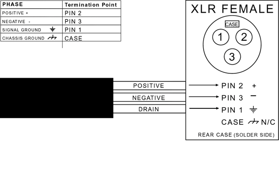
You will need to swap the wires on 2 and 3 on one of the ends that goes to a microphone.
Out of Phase Condenser Microphones - Not Recommended
Hilmar-at-Bose talks about Wiring Two Condenser microphones with a Y cord[5]
I would NOT recommend the out-of-phase Y adapter (or any kind of Y-adapter for that matter) with condenser mics. These mics have build in preamplifiers and connecting the outputs directly will present the mics with the wrong input impedance.
Again, I would only recommend the adapter for dynamic microphones (like for example a Shure SM57). If you want to use KSM109s (which are nice microphones), you may have to use a little mini-mixer to combine the microphone signals. You can still use the XLR phase inverter on one channel to get the cancellation effect. The 109s should work for near field as well as for overhead. For near-field you might have to engage the -15 dB pad on the microphones.
Overhead Condensers
MikeZ-at-Bose suggested:
- The C1000's are great mics. With L1's the way to do overheads is to place the overhead mic stand *behind* the drummer, with the mics pointing slightly toward the audience. Its sort of backwards from how its usually done, but it works really well. You will not need the para EQ if you set the condensers in this way.
Source: MikeZ-at-Bose talking about micing Drums
PA
Definition
PA System or Public Address System
See: PA System on Wikipedia for a common description.
Articles
Stereo / Mono / Distributed_Systems
Phantom Power
Phantom Power Definition
Question: What is a "phantom powered" microphone? Does that mean that the microphone draws its power from a remote source?
Answer: Phantom power is used with condenser microphones. It is called phantom power because there is no obvious external power supply for the condenser mic; the power supply is invisible and therefore a "phantom." The mixer sends voltage up the same wires that the audio is traveling down. Thus, the microphone is receiving the power remotely from the mixer.
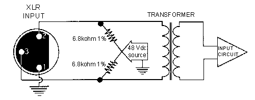
Phantom power is a DC voltage (usually 12-48 volts) used to power the electronics of a condenser microphone. For some (non-electret) condensers it may also be used to provide the polarizing voltage for the element itself. This voltage is supplied through the microphone cable by a mixer equipped with phantom power or by some type of in-line external source. The voltage is equal on Pin 2 and Pin 3 of a typical balanced, XLR-type connector. For a 48 volt phantom source, for example, Pin 2 is 48 VDC and Pin 3 is 48 VDC, both with respect to Pin 1 which is ground (shield).
Because the voltage is exactly the same on Pin 2 and Pin 3, phantom power will have no effect on balanced dynamic microphones: no current will flow since there is no voltage difference across the output. In fact, phantom power supplies have current limiting which will prevent damage to a dynamic microphone even if it is shorted or miswired. In general, balanced dynamic microphones can be connected to phantom powered mixer inputs with no problem.
Source: Shure.com
Will Phantom Power Damage Dynamic Microphones
- Phantom power supplies have current limiting which will prevent damage to a dynamic microphone even if it is shorted or miswired. In general, balanced dynamic microphones can be connected to phantom powered mixer inputs with no problem.
- Source: What is Phantom Power, Shure.com
- As long as your mic cables are all wired properly (balanced, with the correct pin connections) and well made, and you are using decent XLRs everywhere — and all your microphones are modern — there is no problem at all.
Phantom Power Supplied by Bose Systems
Phantom Power Available
Phantom Power is available on
- T4S/T8S ToneMatch® Mixers and T1 ToneMatch Audio Engine 48 volts[6]
When you turn on the Phantom power, it is available on all XLR inputs. It cannot be turned on/off on individual channels.- T1 ToneMatch Audio Engine channels 1, 2, 3
- T4S ToneMatch mixer channels 1, 2, 3, 4
- T8S ToneMatch mixer channels 1, 2, 3, 4, 5, 6, 7, 8
- L1 Model I[7]
- channels 1 and 2 turned on/off individually
- L1 Classic[8]
- channels 1 and 2 turned on/off individually
Phantom Power is available on
- L1 Classic / L1 Model I the Power Stand supplies 24 volts for Phantom Power.[9]
Current Limiting
Bose Phantom power supplies have current limiting which will prevent damage to the Bose device if the connected device attempts to draw too much current.
Turn Down Master Volume Before Turning on Phantom Power
- Please turn down the Master Volume control before turning on phantom power
This will avoid noise being sent out to the powered loudspeakers when you turn on the power.
No Phantom Power
There is no phantom available on
Phantom Power Connected to Bose Systems
Applies to:
- ToneMatch Mixers
- L1 Compact
- S1 Pro System
You may want to connect your Bose Portable PA to an external system using the Line Out. All of the Line Outputs are line-level, balanced outputs. On the T1 ToneMatch Audio Engine, T4S, T8S, L1 Compact, the outputs are 1/4 inch (6.3mm). On the T8S, there are also XLR Outputs.
Will Phantom Power Damage Bose Outputs?
- Will phantom power provided by the external system damage the Bose Portable PA system?
The outputs of Bose Portable PA equipment have circuitry to protect them in case phantom power is turned on in the external system.
24V volt Phantom Power
From Hilmar-at-Bose
That is a somewhat difficult topic. We certainly have tried a KMS105 for live and even for recording with our 24V phantom supply and didn't find any problems. Then again, everybody's ears and taste is a little different, so I can't claim that there really isn't any difference. Going through the Alesis might also change things a little, so it's hard to do an exact apples-to-apples comparison.
From a technical stand-point, it's difficult for me to believe that there are any issues. I haven't taken a KMS 105 apart yet (they ain't cheap !) but most Neuman mics use an internal DC to DC converter and polarize at 200V or so. If any, that should work better with a "proper" 24 V supply because it can provide nearly twice the overall power of a standard 48V supply. Getting more useable DC power was actually one of the reasons why the 24V standard was suggested.
Different microphones do different things with Phantom Power but it's not only the voltage that matters but also the current. The original 48V/6.8kOhm standard was optimized for microphones that needed external polarization and therefore high voltage but nearly no current at all. But this type of microphone is exceedingly rare these days and the phantom power is used either to drive an internal pre-amp or to run an internal voltage-converter or stabilizer. For both cases a supply with lower voltage and higher current (and more overall power) is actually better and hence the 24V/1.2kOhm standard was derived.
I hope I don't bore everybody to death with some math, but let's look at the example of the KMS105. I believe that at nominal 48 V the mic draws about 4mA. That current also goes through the internal 6.8k Ohm resistor of the phantom power supply and leads to voltage "sag". If we use Ohm's law we find that the internal effective resistance of the microphone is about 5 kOhms and that the voltage at the microphone terminals is only 20 V. All the rest is lost inside the supply. If you attach the same microphone to 24V/1.2kOhm supply the voltage sag is much less and the voltage at the microphone terminals comes out to be 19V. It's hard for me to believe that this 1 V difference should make any apprectiable difference in the mics performance.
For an even more power hungry microphone that draws 5mA, the 24V/1.2kOhm supply will actually provide 3 Volts MORE (17V vs. 14V) at the microphone terminals. Sounds a little counterintuitive, but is actually true.
Of course, in the end you have to be the judge of what sounds best to you ears.
Hope that helps
Hilmar
Source: Phantom Power discussion in the Bose Portable PA Community
Questions
If you have questions about this article, please post a message in Phantom Power Discussion in the Bose Portable PA Community
- ↑ Microphone Techniques - Shure Notes
- ↑ Cliff-at-Bose: in Out of Phase Overheads Original post in the Bose® Musicians Community Message Boards
- ↑ Hilmar-at-Bose talks about Wiring Two SM75s with a Y cord Original post in the Bose® Musicians Community Message Boards
- ↑ Hilmar-at-Bose talks about buying an out-of-phase adapter
- ↑ Hilmar-at-Bose talks about out of phase condenser microphones
- ↑ Phantom Power in T1® FAQ
- ↑ Phantom Power in Model I FAQ
- ↑ Phantom Power in Model I FAQ
- ↑ Phantom Power in Model I FAQ
Phase (cancellation, interference)
Phase (cancellation, interference)
Minimum Distance Running Two L1®s in Dual Mono
Phase cancellation can be an issue if you are running Dual Mono (two L1®s from the same mono source). This can be an issue when two or more L1®s are fed the same signal.
The minimum recommended distance for two L1®s running the same signal is 20-50 feet.
Only when fed the same signal, "Interference between line arrays would be more severe [than for non-line-array speakers]. In fact, the current Bose design rules for installing MA12 line arrays recommend ... a spacing between line arrays of between 6 and 15 meters! (20-50 feet)" The same applies to the L1. - Chris-at-Bose [1] (Clarifications added by the author of the quote.)
Note: During a conversation with Chris-at-Bose, he confirmed that the recommendations above are the same for the L1 Model II. ST 15:13, 30 August 2007 (GMT-7)
Theoretical Discussion
Running two inputs 180° out-of-phase puts the peaks and valleys of the sine wave so that they null each other out when summed (see the middle picture below). This has a tendency to cancel out both inputs, and is quite pronounced in the "far" field, but negligible in the "near" field. Normally phase cancellation is undesirable, but when you know what you want (and in this case, what you don't want) then you do it deliberately.
Phase cancellation occurs when two signals of the same frequency are out of phase with each other resulting in either a boost or cut in the overall level of the combined signal.
-- Phase at the Zen Audio Project
If you are suffering from some or all of these, you could be experiencing Phase Interference
- "Hot" and "cold" spots in the audience area
- Tonal coloration
- Poor speech intelligibility
- Lack of music clarity
- Poor gain-before-feedback
- Poor imaging
See: There is an interesting visual presentation of how phase cancellation occurs with two sound sources.
Practical Realities of Phase Interference
See: Phase
Presets
Presets are ToneMatch® Presets.
What is the concept behind ToneMatch® presets, and what are the benefits?
ToneMatch® is a proprietary new technology from Bose that for the first time makes it possible for live musicians anywhere, anytime, to play with recording-studio tonal quality.
The Problem
Most musicians, performers, and entertainers go to enormous lengths to develop their own, unique sound, or tone.
But one of the biggest sources of frustration in finding and then keeping good tone comes from the need to use an instrument pickup or microphone, and a loudspeaker.
The problem is that they all sound different.
They all color the sound of the voice or instrument that’s being amplified.
When musicians hear this coloration, they have a choice: live with the tonal coloration, try to fix it, either themselves or probably better by trying to work with a good sound engineer, or try another microphone or pickup.
Exactly the same thing is true of loudspeakers.
They all sound different.
Again, when musicians hear these tonal changes, they can either live with them, try to fix them, or they can look for another loudspeaker that they like better.
Bose concluded that most musicians are either playing with undesirable tonal coloration from microphones, pickups, and speakers, or are spending a lot of their time and effort trying to fix it.
Using a Gifted Studio Engineer
Now, one way you could get rid of the tonal coloration would be to give each musician a good sound engineer, who could listen to the tonal changes and take the time necessary to make adjustments on the sophisticated equipment needed to do this kind of work.
With ToneMatch technology that work has already been done.
Building the Studio Engineer into the Equipment
Bose has been working with many musicians and have listened to a wide variety of instruments, microphones and pickups connected to the L1 system, and for each, has taken the time necessary to make the adjustments to the sophisticated equipment necessary to optimize the tone.
Then, they stored the settings inside the T1, ready to be recalled at the touch of a button by any musician, anywhere in the world.
ToneMatch Partners
In order to provide the largest library of ToneMatch® presets, Bose has been working with a growing number of manufacturers to develop these studio-quality settings for their microphones and instruments.
You can watch video interviews with people from those manufacturers talking about ToneMatch technology.
How the Loudspeaker Affects ToneMatch Performance
It should be stressed that the loudspeaker plays a crucial role in delivering this kind of tonal improvement.
The L1 system is unique because it delivers the improvement consistently across the stage and throughout the audience in a way no conventional speaker can.
How ToneMatch Works Together with zEQ
You might not want to change anything once you hear the improvement provided by a ToneMatch® preset.
But if you do, there’s another key new technology built into the T1 ToneMatch Audio Engine for doing just that.
It’s called zEQ.
First, you select you ToneMatch preset.
Then, you turn the rotary selector on the T1 to zEQ.
At this point, three controls on the T1 are automatically programmed to provide tonal enhancements for your voice or instrument.
If you’ve selected a preset for bass guitar, for example, the three controls are programmed to allow tonal enhancements for that particular instrument. If you choose a vocal mic, the controls are programmed for vocals, and so on.
It is the combination of the new tone-shaping technologies in the T1 engine, married to the exceptional coverage and high degree of portability in the new L1 model II system, that compels Bose to say that this is the most advanced system they’ve ever offered to musicians.
Related Resources
- A Personal Take on ToneMatch® Technology - presentation from Ken-at-Bose (video)
- ToneMatch® Presets for the T1 ToneMatch® Audio Engine
- What others are saying about ToneMatch® Interviews with ToneMatch® Partners
- zEQ
- Presets
- What happens when you bypass a ToneMatch® Preset?
See also: Presets
Processors
These devices are often placed between an instrument and an amplification system to modify the tone and other aspects of the sound of the instrument. Some musicians are using these in place of backline amplifiers and run their processors directly into their Bose System. Typically these can be run into
- Any ToneMatch Mixer input
- L1 Compact channel 2 (ToneMatch switch set to Line Level)
- S1 Pro System channel 1, 2, or Aux Input/Channel 3
- Channels 3 or 4 of the PS1 powerstand. They can also be run to Channels 1 or 2 with preset #00.
- Related Articles
- Acoustic Guitar for Acoustic Guitar Processors
Proximity Effect
The bass response of all directional microphones is increased as the signal source - your voice - comes closer to the mic capsule. This is called Proximity Effect and it becomes apparent at a range of one foot and increases as the distance of mouth to mic decreases.
For speakers or singers with high or thin voices, proximity effect can boost the bass, filling out the sound. - source Shure Notes
This is a stub. Please add links and references.
Reverberant Field
In the reverberant field, reflections from walls and other objects may be just as strong as the direct sound from the source. acousticvibration.com
See also: L1® vs B1 Bass Module Fall Off with Distance
Sound Pressure Level
The term most often used in measuring the magnitude of sound. It is a relative quantity in that it is the ratio between the actual SOUND PRESSURE and a fixed reference pressure. This reference pressure is usually that of the THRESHOLD OF HEARING which has been internationally agreed upon as having the value .0002 dynes/cm2.
SPL may be measured with a SOUND LEVEL METER weighted according to a specific frequency response pattern and termed SOUND LEVEL. The electroacoustic equivalent to SPL is measured with a VU METER.
— Source: SOUND PRESSURE LEVEL (SPL) http://www.sfu.ca
| Change in Sound Pressure Level dB | Approximate change in acoustic pressure | percentage change in acoustic pressure | Human Subjective Reaction |
| 1dB | 1.1 | 10% | Can′t detect |
| 3dB | 1.4 | 40% | Minimum change we can remember |
| 6dB | 2.0 | 100% | Pressure doubling, significant change |
| 10dB | 3.3 | 330% | Subjective doubling |
| 20dB | 10.0 | 1000% | Very noticeable change |
— Source: http://www.diracdelta.co.uk
Spectral Identification
Vocabulary for discussing sound.
Cliff-at-Bose
Well, as it appears to me, there are no rules for communicating about audio qualities right now, something that is essential for a functional language to work. We have a whole truck-load of words, all of which mean different things to everyone. Tower of Babel. A lot of these words have been invented, I think, by the audio press. Imagine making up language for what you think you heard over the differences in audio qualities between normal and "special" AC power cords or different wood that you laid your speaker cables next to. Honest. I have seen this and much more.
I'm going to post the 10-word vocabulary I have been teaching here at Bose. "your rules" hit me funny, like it's my ball and you have to play this way or forget it. It's not like this is the script carved on the holy tablets by God, or whatnot. It's just an attempt, a proposal, for any rule where there really aren't any. I think that if we can at least agree on 10 words, it's a start. Actually, these words are a "middle man" to what we really need to do: Hear, listen (the combined activity of taking in audio information, thinking and concluding) and identify in real engineering terms. Like, for instance, a "nasal" quality is heard, the thought process says "aha, too much level in the 1KHz octave" and then you can do something about it, like reach for the 1KHz part of an equalizer and make it sound normal. The words describe familiar qualities we are all familiar with, many having to do with our knowledge of how normal human speech sounds.
But, for this discussion, here are the 10 words, which describe a 1 octave excess level in the stated center of that octave (these are all "ISO standard center frequencies"). These can be used anywhere but hopefully for better communication about qualities about our system, for better or for worse:
| woofy | 31Hz | octave | deep bass |
| boomy | 62 Hz | octave | bass |
| punchy | 125 Hz | octave | mid bass |
| chesty | 250 Hz | octave | upper bass |
| honky | 500 Hz | octave | low midrange |
| nasal | 1,000 Hz | octave | midrange |
| quacky | 2,000 Hz | octave | upper mid-range |
| shrill | 4,000 Hz | octave | high midrange (the most annoying octave to be accented) |
| spitty | 8,000 Hz | octave | high frequency Cliff demonstrates "Spitty" |
| air | 16,000 Hz | octave | very high frequency |
From Kyle-at-Bose
Here are some cuts from Cliff's Spectral Identification disc. Personally, there have been a few key people here at Bose who have helped broaden my listening capabilities by teaching me how and what to listen to. Cliff is definitely one of those persons who have helped me tune my senses. I hope these tracks are as helpful to you as they were to me. In addition, also consider the audio ear training course from Dave Moulton called " Golden Ears. Although it's much more catered to the intricacies of recording music, it's very helpful in general (By the way it’s a lengthy 8 discs I think). Here goes with Cliff’s recordings...
| Play Now (double-click a track to play it) | Download |
|
|
|
Or download Bose_ListeningReference.exe (91 megabytes)
ToneMatch®
What is the concept behind ToneMatch® presets, and what are the benefits?
ToneMatch® is a proprietary new technology from Bose that for the first time makes it possible for live musicians anywhere, anytime, to play with recording-studio tonal quality.
The Problem
Most musicians, performers, and entertainers go to enormous lengths to develop their own, unique sound, or tone.
But one of the biggest sources of frustration in finding and then keeping good tone comes from the need to use an instrument pickup or microphone, and a loudspeaker.
The problem is that they all sound different.
They all color the sound of the voice or instrument that’s being amplified.
When musicians hear this coloration, they have a choice: live with the tonal coloration, try to fix it, either themselves or probably better by trying to work with a good sound engineer, or try another microphone or pickup.
Exactly the same thing is true of loudspeakers.
They all sound different.
Again, when musicians hear these tonal changes, they can either live with them, try to fix them, or they can look for another loudspeaker that they like better.
Bose concluded that most musicians are either playing with undesirable tonal coloration from microphones, pickups, and speakers, or are spending a lot of their time and effort trying to fix it.
Using a Gifted Studio Engineer
Now, one way you could get rid of the tonal coloration would be to give each musician a good sound engineer, who could listen to the tonal changes and take the time necessary to make adjustments on the sophisticated equipment needed to do this kind of work.
With ToneMatch technology that work has already been done.
Building the Studio Engineer into the Equipment
Bose has been working with many musicians and have listened to a wide variety of instruments, microphones and pickups connected to the L1 system, and for each, has taken the time necessary to make the adjustments to the sophisticated equipment necessary to optimize the tone.
Then, they stored the settings inside the T1, ready to be recalled at the touch of a button by any musician, anywhere in the world.
ToneMatch Partners
In order to provide the largest library of ToneMatch® presets, Bose has been working with a growing number of manufacturers to develop these studio-quality settings for their microphones and instruments.
You can watch video interviews with people from those manufacturers talking about ToneMatch technology.
How the Loudspeaker Affects ToneMatch Performance
It should be stressed that the loudspeaker plays a crucial role in delivering this kind of tonal improvement.
The L1 system is unique because it delivers the improvement consistently across the stage and throughout the audience in a way no conventional speaker can.
How ToneMatch Works Together with zEQ
You might not want to change anything once you hear the improvement provided by a ToneMatch® preset.
But if you do, there’s another key new technology built into the T1 ToneMatch Audio Engine for doing just that.
It’s called zEQ.
First, you select you ToneMatch preset.
Then, you turn the rotary selector on the T1 to zEQ.
At this point, three controls on the T1 are automatically programmed to provide tonal enhancements for your voice or instrument.
If you’ve selected a preset for bass guitar, for example, the three controls are programmed to allow tonal enhancements for that particular instrument. If you choose a vocal mic, the controls are programmed for vocals, and so on.
It is the combination of the new tone-shaping technologies in the T1 engine, married to the exceptional coverage and high degree of portability in the new L1 model II system, that compels Bose to say that this is the most advanced system they’ve ever offered to musicians.
Related Resources
- A Personal Take on ToneMatch® Technology - presentation from Ken-at-Bose (video)
- ToneMatch® Presets for the T1 ToneMatch® Audio Engine
- What others are saying about ToneMatch® Interviews with ToneMatch® Partners
- zEQ
- Presets
- What happens when you bypass a ToneMatch® Preset?
Triple System Amplification
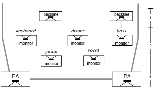
Triple Amplification System also known as the Three-Tier Approach
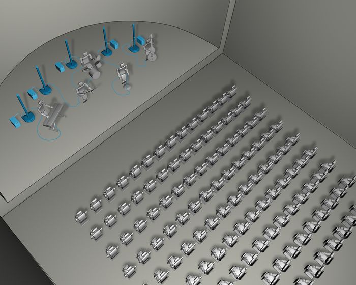
The three separate amplification systems comprising a triple system are shown: the backline system (1) is a holdover from the earlier individual-instrument approach because these amplifiers are considered an essential part of certain instruments’ sounds. The monitor system (2) is pointed away from the audience and towards the musicians, and is intended to give each musician their own mix. The PA system (3) projects sound into the audience but not onto the stage.
This originally appeared on page 22 of the Bose White Paper.
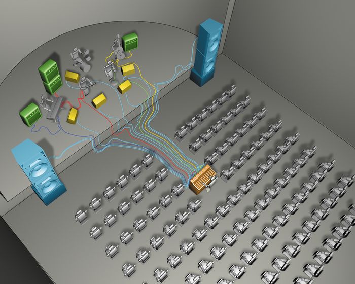
Here is another view.
You can contrast this with an L1® setup.
Volume
Notes about Volume
Hilmar-at-Bose
Originally posted by Hilmar-at-Bose: March 29, 2004
There is really a bunch of things coming into play when things get loud, most of them not good. Since there are a lot of them, this will be a long post (I apologize).
There a bunch of non-linear effects that happens in your own brain and auditory system. A very clear indication that the human auditory system is not really designed for very high sound pressure levels is the fact that speech intelligibility drops rapidly with sound pressure level (all other things being equal) and is generally very poor above 100 dB SPL. Here are some of the physiological reasons why this is the case:
1. The first one is the "equal loudness curve" (sometime also referred to as Fletcher-Munson curves) that Steve has already mentioned (ed. see below). The main effect is that you have to roll of the low end as level go up (or boost it as the level goes down). It basically compensates that the way humans turn sound pressure (physical property of sound) into loudness (a perception in our brain) is really not the same for all frequencies.
2. The second is the “acoustic reflex” or “middle ear reflex”. It’s a built-in protection in the middle ear that kicks in at sound levels above about 80 dB SPL. Normally sound is picked up by the ear-drum and then transferred through three tiny little bones in the middle ear to the inner ear. These bones that are basically a system of levers that transport vibration in a certain way. If it gets too loud a tiny muscles in the middle ear contracts and changes the coupling between the bones. It basically makes the levers less efficient and that protects the bones themselves and the inner ear from potentially harmful sound level. That fact also gives you some appreciation of what “evolution” regards as excessive sound levels and for what type of sound pressure levels the hearing system is basically designed for. So basically the acoustic reflex is a non-linear reduction in sound pressure level and its also frequency dependent
3. In the inner ear, vibrations are converted into never impulses by the so-called “hair cells”. These cells get wiggled by the incoming sound and as a result of that they send a nerve impulse. These impulses are all-or-nothing, i.e. they all have the same strength. More sound level leads to the hair cells firing more frequently, but not to any changes in pulse amplitude. Now the hair cells have a maximum firing rate, above which they just can’t react to more stimulus anymore. The only way to detect more sound pressure is to look at the behavior of a large group of cells which is much less exact as if every single cell would still be operating in its linear range.
4. Another effect is called “masking”. Its due to the way that vibration is transferred from the middle ear to the hair cells (through the so-called basilar membrane). Normally every hair cell is tuned to a specific frequency, but since the tuning is not perfect it will also react to frequencies that are not. The result of this is that the perception of a certain tone can be influenced by the presence or absence of a tone at a different frequency. The effect is highly asymmetric, i.e. low tones can mask high tones but high tones cannot mask low tones. Again this effect is more pronounced at higher levels and a single string bass note can drown out a lot of other sounds.
In summary, above a certain level you will operate your auditory system at a point it wasn’t really designed for and that will result in a lot of “internal distortion” that interferes with clarity, speech intelligibility and overall enjoyment. In other words you are overdriving your input.
There are also some problems with the sound system and the room.
5. Nearly all loudspeakers these days are so-called “dynamic” loudspeakers; i.e. they run current through a moving coil in a static magnetic field. The basic principle has a non-linear component to it, which gets worse as the sound level increases. You can actually operate a loudspeaker WITHOUT a magnet and you will get to hear only the non-linear component.
6. There are a few more mechanisms that can generate distortion at higher levels: these include voice coil heat up, excursion limits, non-ideal magnetic fields, non-linear (i.e. overextended) surrounds and spiders, etc. Off course in a high quality loudspeaker such as ours, these things are all carefully designed, controlled and optimized but they are still all present and may under certain circumstances at very high stress levels product audible effects.
7. In many rooms something (ceiling tiles, curtain rods, stuff in a drawer etc.) can rattle when excited hard enough and that contributes to background noise
8. When you play louder, the audience is likely to talk (or yell) louder (to have a conversation or simply to order another drink) and that again raises the level of the background noise.
9. If there are microphones (or acoustic guitar pickups) involved, these will not only pickup the intended sound but also the sound radiated from the loudspeaker. If you keep cranking that ultimately leads to feedback, but even way before that point these picked up sounds will change the frequency response and time signature of the original signal
So turning up does not only makes it louder, it also has a variety of unwanted side effects. In the end, it is an artistic decision, but maybe being aware of all the things that can or will happen can help making in making this decision.
Hope that helps
Hilmar
Source: volume
Steve-at-Bose
One other thing I'll throw at you for consideration, our ears have a different "eq curve" at different volumes ... yup, believe it or not, it may be that your ears are the "problem" here.
Check this ... go to Google and type in "Equal loudness curves" and you will get a bunch of hits that can explain it in many ways (even interactively). (edit: see Equal Loudness)
Here is an example from the studies, the threshold of hearing for a 1 KHz tone is about 3dB SPL. That is, for the average human ear, until you turn up your 1 KHz to 3dB SPL, it will not be loud enough.
Now hold on to your hat, guess what the threshold of hearing is for a 20Hz tone. Almost 80 dB SPL. That is a HUGE difference, about 77 dB SPL.
And it gets trickier, as you turn up louder and louder, the equal loudness curves change ... that is the "threshold of hearing" curve looks different from the "threshold of pain" curve.
Anyway, use the net to learn more about this. It may help to explain why instruments sound so different at home volumes versus stage volumes.
Source: volume
Ken-at-Bose
Original Contributor: KJacob
Using a typical triple amplification system, a professional front-of-house mixer rides vocals, varies the level of horn sections and rides (and often misses) lead solos. They do this because they and not you can hear a mix over the mains “out front”.
The Bose® Personalized Amplification System™ family of products changes all this. Now you can hear the mix your audience hears. Are the vocals too soft? Now you can do something about it. Turn it up (of sing louder)! Or, more probable, turn everything else down! Is your guitar solo easily heard? Are the drums too loud? Don’t get mad. Work together as a band and play the tune right. Play with dynamics. When that sax solo comes in, drop the whole band’s level so much that every little juicy nuance can be heard. How will you know? You will hear it. Listen! Support the lead instrument by playing quieter, or less, or most likely (the best-ever approach), don’t play at all! It might surprise you to know that many of the top professional players in the world are most revered and respected for what they don’t play than for what they do play. It’s exactly the same as a “playmaker” in a team sport. Yeah, the big scorers get the headlines. But the players that make the most assists quickly become the most valuable players. Delivering the song you are playing is the same as making a goal in sports.
And about playing loud: This can be real exciting, but not as a steady thing. Don’t hammer your audiences into numbness without a letup. And don’t numb your whole band by a steady diet of loud. Everyone appreciates a letup. Treat yourselves and your audiences to the knockout punch, but make it infinitely more dramatic when you launch it from almost dead quiet. Showbiz requires dramatic over-exaggeration for a memorable effect. Combining loud play with really quiet play is the best way to get the point across. This might be a new world of playing for you. Try it. Now you can hear it and now you can do something about it. It’s interesting: most “hit” records are produced to sound loud, and it is done with a big sacrifice in dynamic range or peak-to-average sound. Call this “punch”. You can make it sound better than a record. Mix it live by playing it right.
