Difference between revisions of "PS1 Powerstand Connections/Line Out/Insert"
(first ed) |
m (→Line Out from Insert Point) |
||
| Line 4: | Line 4: | ||
* post {{R1}} Channel Level | * post {{R1}} Channel Level | ||
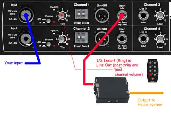
| − | For Channels One or Two insert a 1/4 inch cable halfway into the Insert jack to get a signal that is controlled by the volume control on the Remote. This is also known as the [[Half Insert]] method. For more information about 1/4 cables see [[TRS|Tip Ring Sleeve connections]]. | + | For Channels One or Two insert a 1/4 inch cable halfway into the Insert jack to get a signal that is controlled by the volume control on the Remote. This is also known as the [[Half Insert]] method. For more information about 1/4 cables see [[TRS|Tip Ring Sleeve connections]]. The rectangular box shown below the input panel is a [[DI]], used to output the signal to a console or house system. |
[[Image:PS1LineOutInsert.jpg]] | [[Image:PS1LineOutInsert.jpg]] | ||
Revision as of 14:15, 14 November 2006
Line Out from Insert Point
- access from the "ring" connection at the Insert Point
- post trim
- post R1 Remote Channel Level
For Channels One or Two insert a 1/4 inch cable halfway into the Insert jack to get a signal that is controlled by the volume control on the Remote. This is also known as the Half Insert method. For more information about 1/4 cables see Tip Ring Sleeve connections. The rectangular box shown below the input panel is a DI, used to output the signal to a console or house system.
