Difference between revisions of "Mixer / Yamaha / MG124 CX"
m |
m (→Settings on the L1® Input Panel) |
||
| (5 intermediate revisions by the same user not shown) | |||
| Line 1: | Line 1: | ||
| − | To use a Yamaha MG124 CX Mixer with the {{Model II}} | + | <table><tr> |
| + | <td valign="top" width="250">__TOC__</td> | ||
| + | <td valign="top">To use a Yamaha MG124 CX Mixer with the {{Model II}} | ||
| + | </td> | ||
| + | </tr></table> | ||
| + | |||
| + | |||
==== Overview ==== | ==== Overview ==== | ||
On the mixer | On the mixer | ||
| − | * | + | * Pan all the inputs hard LEFT |
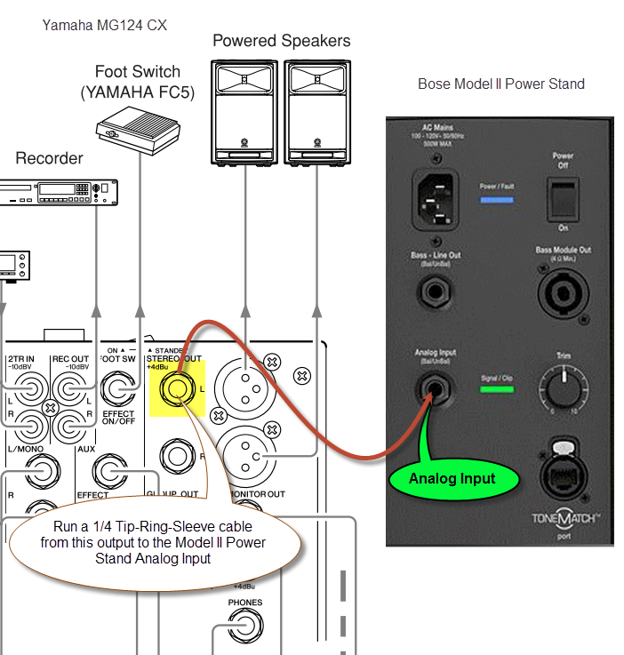
| − | * | + | * Run a line out of the LEFT output to the Model II Power Stand Analog input (cable details below) |
[[Image:YamahaMG124 to Model II Power Stand Analog Input.png]] | [[Image:YamahaMG124 to Model II Power Stand Analog Input.png]] | ||
| + | |||
| + | ==== Settings on the L1® Input Panel ==== | ||
| + | Start off with the Input Trim at '''3''' and adjust if necessary so that the Signal/Clip light stays green most of the time. Occasional flickers of yellow are okay. If it is flickering or solid red, turn down the Input Trim. | ||
| + | |||
| + | [[Image:ModelIIInputsForTwoLT1.png]] | ||
==== Cable Details ==== | ==== Cable Details ==== | ||
| Line 30: | Line 41: | ||
</td></tr></table> | </td></tr></table> | ||
| + | === Documents === | ||
| + | * {{Model II}} | ||
| + | * [http://download.yamaha.com/api/asset/file?language=en&site=countrysite-master.prod.exp.yamaha.com&asset_id=8043 Yamaha MG124CX/MC124 Owner's Manual] | ||
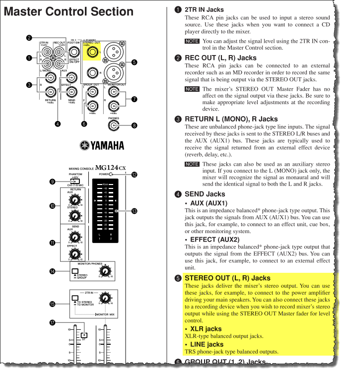
| + | [[Image:YamahaMG124 Output.png]] | ||
---- | ---- | ||
[[Category:Mixer]] | [[Category:Mixer]] | ||
[[Category:Yamaha]] | [[Category:Yamaha]] | ||
Latest revision as of 13:02, 19 September 2012
| To use a Yamaha MG124 CX Mixer with the L1 Model II |
Overview
On the mixer
- Pan all the inputs hard LEFT
- Run a line out of the LEFT output to the Model II Power Stand Analog input (cable details below)
Settings on the L1® Input Panel
Start off with the Input Trim at 3 and adjust if necessary so that the Signal/Clip light stays green most of the time. Occasional flickers of yellow are okay. If it is flickering or solid red, turn down the Input Trim.
Cable Details
¼ inch jack inch to ¼ inch
|
This mixer has ¼ inch jack balanced outputs. Any of the cables shown below should work.
¼ Inch Tip-Ring-Sleeve (balanced) to ¼ Inch Tip-Ring-Sleeve (balanced)The output of this mixer is balanced, and the input on the Model II Power Stand is also balanced, so this is the preferred method. ¼ Inch Tip-Sleeve (unbalanced) to ¼ Inch Tip-Sleeve (unbalanced)¼ Inch Tip-Ring-Sleeve (balanced) to ¼ Inch Tip-Sleeve (unbalanced)
|


