File:ModelIIIOPanel.png
http://worldwide.bose.com/pro/en_us/web/l1_model2/page.html?term=panel_diagram&view=general_linked
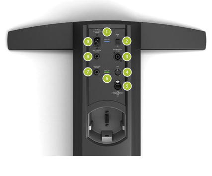
Power/Fault LED - Indicates power status.
Blue = system on
Red = system faultPower switch - Switches the system on and off.
Bass Module Out - Bass output signal for driving one or two B1 bass modules or one B2 bass module.
Trim - Adjusts the level of the analog input signal.
ToneMatch® port - Digital audio and power connection for the optional T1 ToneMatch audio engine.
Signal/Clip LED - Indicates status of the analog input signal.
Green = normal input
Yellow = input approaching clipping
Red = input clippingAnalog Input - A line-level analog input. Accepts a ¼" TRS phone cable. Used for an instrument or other audio source.
Bass - Line Out- Post-DSP bass signal output. Accepts a ¼" TRS phone cable. Used to drive a PackLite® power amplifier.
AC Mains - AC power input connector.
File history
Click on a date/time to view the file as it appeared at that time.
| Date/Time | Thumbnail | Dimensions | User | Comment | |
|---|---|---|---|---|---|
| current | 16:31, 21 November 2014 |  | 427 × 355 (59 KB) | ST (talk | contribs) | http://worldwide.bose.com/pro/en_us/web/l1_model2/page.html?term=panel_diagram&view=general_linked <html> <ul> <li><p><strong>Power/Fault LED - </strong>Indicates power status.<br>Blue = system on<br>Red = system fault</p></li> <li><p><strong>Power swi |
- You cannot overwrite this file.
File usage
The following 4 pages link to this file:
