From Prototype to Product
Contents
Introduction
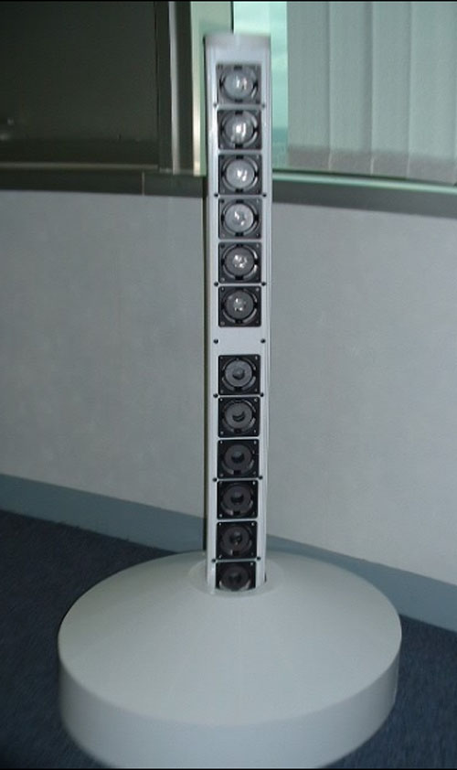
Around 2002, enough testing of the 2nd Generation Prototype had been conducted for Bose to feel confident that the concept worked and should be commercialized.
The effort to convert the concept into a product began.
Integral Bass Enclosure
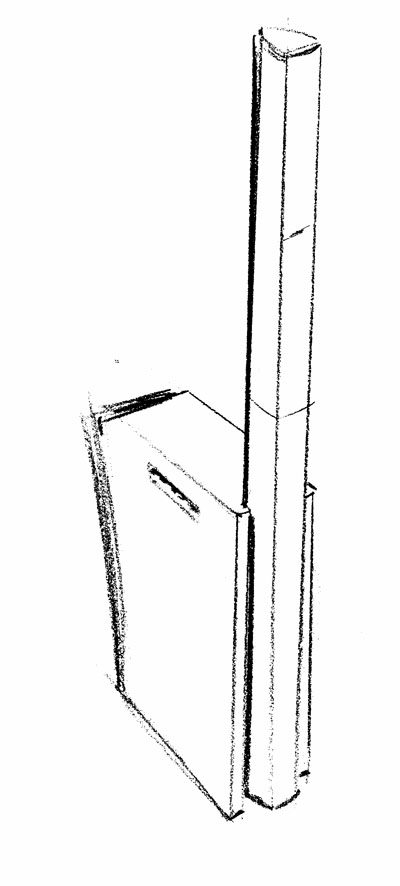
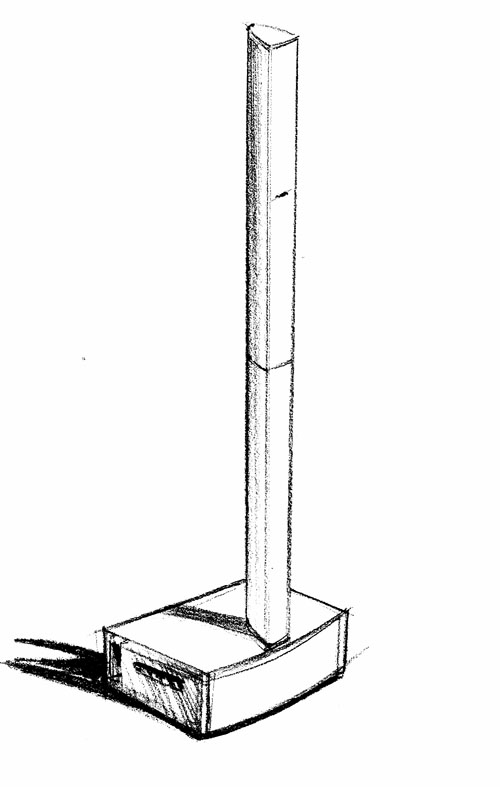
Originally, a bass enclosure integrated into the base that held the mid-high frequency line array was considered.
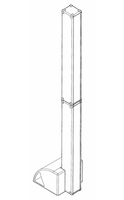
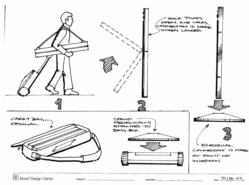
A number of possible configurations were sketched as shown in the drawings below.
Bass box vertical...
Bass box horizontal...
More of a wood guitar amp feel...
Showing how a musician might pack and carry the gear...
Some of the early ideas stuck (electrical connection between the amps and the speakers is made when you plug in the speaker (no speaker wires) and some did not (the folding speaker connections -- they were judged to be too heavy to carry together.)
The "optional" carry bag became an included item.
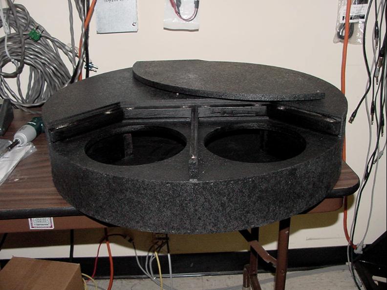
Some prototypes of the integral "bass-base" were made in the wood shop...
In this picture only the bottom half of the Cylindrical Radiator is shown.
Ultimately, the concept of integrated bass was abandoned. It was judged too bulky to carry too bulky in appearance.
Separate Bass
The notion of a separate bass enclosure was considered next.
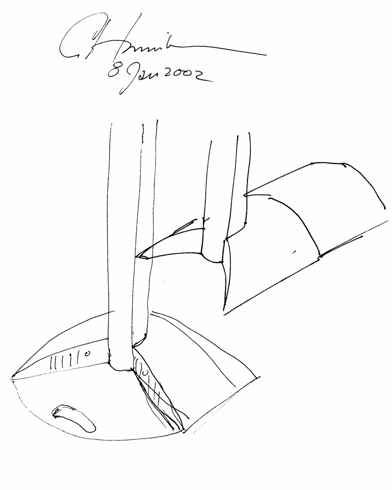
Here's an early sketch from Cliff about one such concept. This was rejected because it ate up to much stage depth.
The Invention of the B1 Bass Module
A Bose MB4 was used for our 2nd generation prototypes. It worked very well, but there were two issues: it was a little bulky to carry, and it was too much bass for some instruments including most guitars, horns, and keyboards.
It was Paul Fidlin (Paul-at-Bose from the Bose® Pro Portable PA Community) (with some input from Wolf from The Linemen) who had led the development of the MB4 and was leading the development of what would be called the L1 Classic, that had the idea of cutting the MB4 in half.
That solved both problems together.
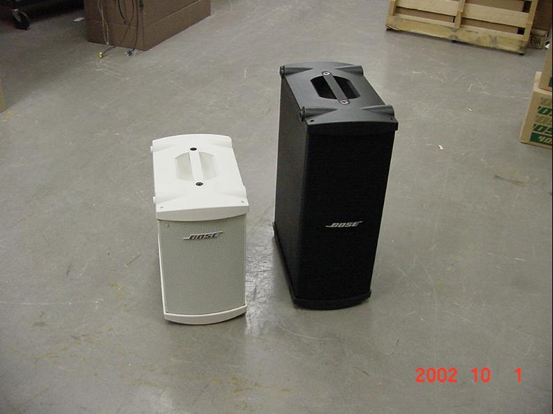
This photo shows the MB4 (right) next to the first cosmetic prototype of what would be called the B1 bass enclosure.
This photo is taken only 13 months before launch. And ToneMatch® technology hadn't even been invented yet.
Creation of the Power Stand
At this point, things moved quickly toward what we now know as the L1 Classic.
With the bass enclosure separated, the duty of the stand was now to hold up the line array speaker and house the electronics.
Logically, the stand need be no more than a circle. This is the most efficient shape to "hold up" the array.
But when the need for inputs and outputs and user controls was considered, it became clear that trying to wrap that around a curve would be expensive and confusing.
That is where the "D" shape of the Classic power stand came from.
This is the first known sketch showing the canonical "D" shape. It's from March of 02.
As you can see, at this point the interface is very simple.
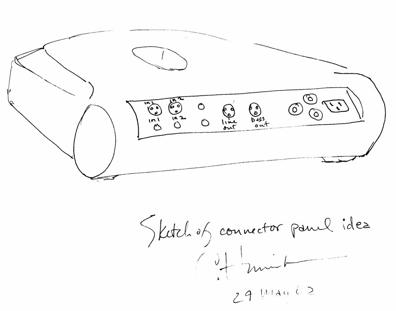
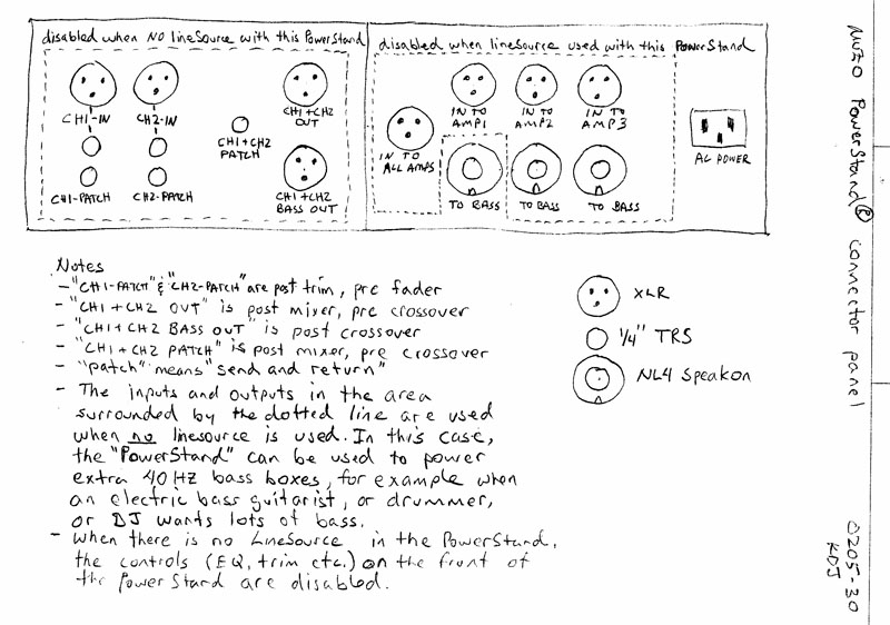
Here's a sketch showing a refinement of the I/O and user controls.
It's May 30, 2002, and there's STILL no ToneMatch.
Two Piece Array Design
One of the most interesting things about commercializing the L1 system was the mechanical design.
Pete Santoro figured out how the two sections of the array snapped together and how the lower section snapped into the power stand.
This is a very tricky design because if you think about it, the 7 foot (2 meter) array is a gigantic lever operating on the poor power stand. Someone exerting a small force at the top of the array can translate to huge forces a the junction of the array with the power stand. This took a lot of creativity and prototyping to get right.
The junction between the two array sections was also tricky. The array sections aren't light. You have to lift the top section and precisely lower it onto the bottom section. The bayonet mechanism that Peter came up with helps to fix and strengthen the joint between the two sections but it also make it pretty easy to line up the two sections and drop the top into the bottom without much fuss.
The "floating" electrical connections between the top and bottom arrays, and the bottom array and the power stand are a small detail, but an important one. The connectors float, so that they don't get worn out with thousands of insertions. This too was Peter's thinking.
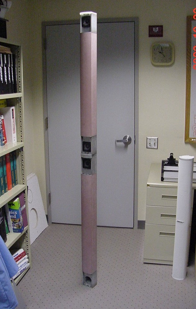
A mechanical prototype is shown where we were testing the mechanical connections between top and bottom arrays. The pink plastic is there to provide the right weight and heft so we could test the mechanical design.
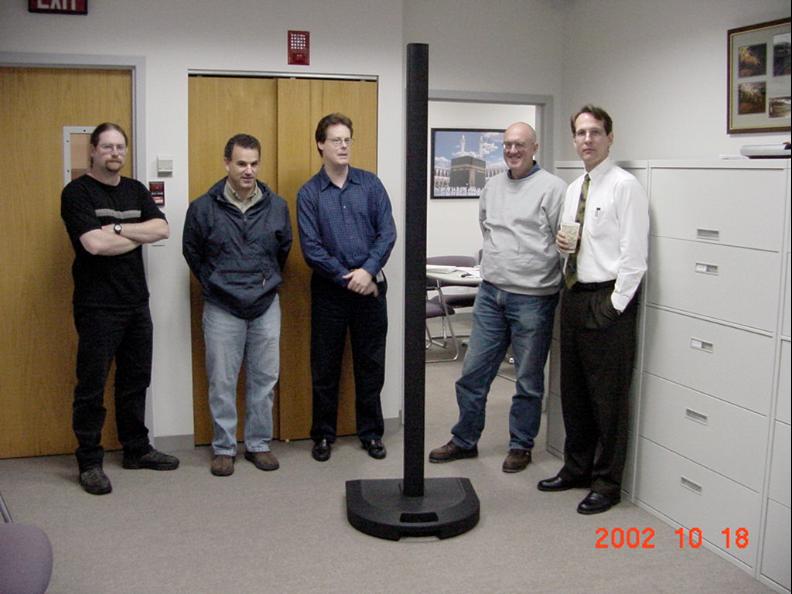
The industrial design was done by Rich Carbone (second from left).
He was asked by Ken to make a "black icicle that had dropped to earth from outer space" -- something that was both instantly recognizable and yet was utterly unobtrusive to the music.
Bose won a major design award from the most prestigious professional organization of industrial designers for this design.
In this photo, the first cosmetic prototype, made in the model shop, has just been assembled.
(Left to right: Pete, Rich, Paul, Cliff, Ken)
The photo is dated October 18, 2002, just less than a year before launch.
Inclusion of ToneMatch
ToneMatch technology was added last. It was Hilmar (Hilmar-at-Bose from the Bose® Pro Portable PA Community) that was able to fit the technology onto the DSP he was using on the product. Paul and Ken had to choose a very simple mechanical control for selecting one of 100 different presets.
