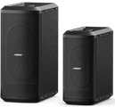
L1® Model I
Contents
|
Announced March 29, 2007
|
|||||||||||||||||||||||||||||||||||||||||||||||||||||||||||||||||||||||||
|
How to Tell the Difference Between Bose Portable PA ModelsThis is how to tell which L1®, S1 Pro, or F1 unit you have.
Compatibility with Other Members of the L1® Family of ProductsCylindrical Radiator®sCylindrical Radiator®s are not interchangeable across modelsSpecifically (and without exception)
T1 ToneMatch® Audio Engine, T4S/T8S ToneMatch® Mixers
PackLite® power amplifier Model A1
B1 Bass Module
B2 Bass Module
|
||||||||||||||||||||||||||||||||||||||||||||||||||||||||||||||||||||||||||
Documentation
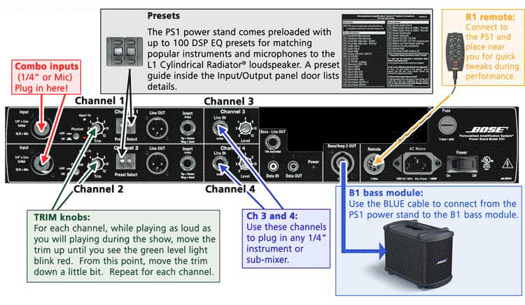
Input Section
Entire Input / Output Panel
full sized version of the image
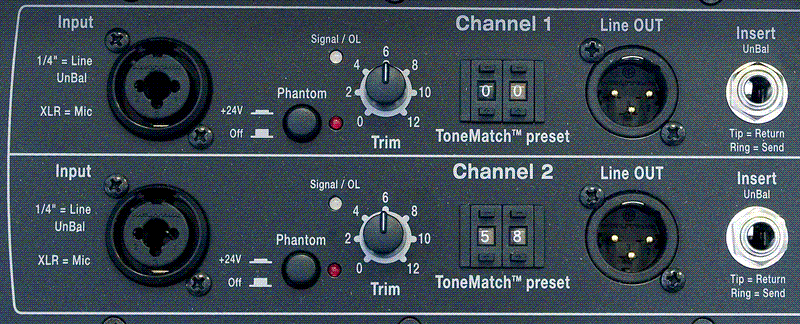
Channels 1 & 2
full sized version of the image
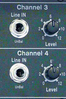
Channels 3 & 4
full sized version of the image
Output Section
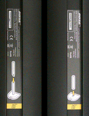
Orange Label
full sized version of the image
Cylindrical Radiator Sections
L1™ Model I L1 Cylindrical Radiator® loudspeaker top and bottom sections showing orange L1™ labels.
full sized version of the image
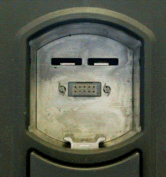
Boot
Note the 'flange' at the back edge of the boot (appears at the bottom of the silver colored recess). This prevents you from inserting the L1 Classic Cylindrical Radiator into the L1 Model I Power Stand.
full sized version of the image
What do the LEDs mean?
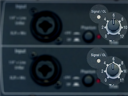
Signal/OL LEDs: Channels 1 and 2
There are two LEDs on the PS1 Power Stand (Classic) / Model I near the Trim knob labelled Signal/OL -- one for Channel 1 and another for Channel 2.
These LEDs indicate when the signal level channel's preamplifier reaches certain important thresholds. The trim controls located near the LEDs adjust the amount of gain in the preamplifier.
- The LEDs turn from off → green when the signal level exceeds a small amount.
- The LEDs turn from green → red when the signal reaches a level that's about 10 dB below a level that would clip the preamp and cause objectionable distortion.
When the LED is off (but you are playing an instrument you think is connected to the PS1 or singing/talking into a microphone you think is connected): Increase the level of the trim control. If the LED still does not turn green or red, check instrument/microphone and cables to the PS1.
When you see green only: This indicates that there's some signal in the channel but not enough. While singing or playing the loudest you ever plan to in the performance, increase the trim level until the LED is only flickering red. This is the optimal gain.
When you see red most of the time: Decrease the trim level until you see only flickering red. This is the optimal gain.
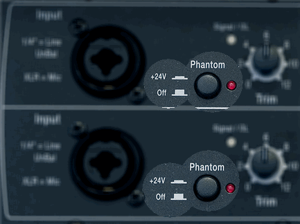
Phantom Power LEDs: Channels 1 and 2
The LEDs near the Phantom Power button are either off or red when phantom power is turned on. — more information about Phantom Power
Power / System Status LED
This LED normally is a steady green when the power is on.
If it is not lit or if it is yellow/amber, contact Support.
Note: This LED may briefly flicker yellow /amber when the power is first turned on; this is normal. Within a couple of seconds, it should settle to a steady green.
Rear Panel Walkthrough
Connecting Other Equipment (inputs)
Connector Types
This section is an overview of connections you can make from a other equipment (mixer, music storage device, etc.) to the PS1 Power Stand (Classic) / Model I.
Audio equipment inputs and outputs are either balanced (three conductors) or unbalanced (two conductors). Balanced signals have the potential to be more resistant to hum and noise.
In addition different kinds of connectors are used for the input and outputs.
Here are the main types:
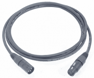
- XLR, male (prongs) and female (receptacles for prongs), usually balanced
- ¼ inch, male (shaft) and female (receptacle for shaft), balanced (tip-ring-sleeve on shaft) or unbalanced (tip-sleeve)
- RCA, male and female, always unbalanced
- 1/8 inch mini (male and female), balanced (tip-ring-sleeve on shaft) or unbalanced (tip-sleeve)
Cable Types and Connection to the PS1
Note: The PS1 Power Stand (Classic) / Model I Channels 1 and 2 ¼ inch inputs are unbalanced. There are many kinds of cables that will work but no connection that uses the ¼ input will be balanced because the internal connection is unbalanced.
XLR (balanced) to XLR (balanced)
This is the same as a microphone cable but is also used to connect a balanced line output to a balanced line input.
¼ Inch Tip-Sleeve (unbalanced) to ¼ Inch Tip-Sleeve (unbalanced)
These cables are prone to noise if you are running long lines (greater than 20 feet). Consider using shorter cable runs, or running a balanced line. You can use a short unbalanced cable to a DI or Direct Box (to convert from unbalanced to balanced) and run an XLR to XLR cable from the Direct Box to the Bose System.
¼ Inch Tip-Ring-Sleeve (balanced) to ¼ Inch Tip-Sleeve (unbalanced)
No issues.
¼ Inch Tip-Ring-Sleeve (balanced) to ¼ Inch Tip-Ring-Sleeve (balanced)
No issues but no better than a simple ¼ Inch Tip-Sleeve to Tip-Sleeve cable because the ¼ Inch input on the Bose System is Tip-Sleeve (unbalanced).
XLR (balanced) to ¼ Inch Tip-Ring-Sleeve (balanced)
No issues but because all four ¼ Inch inputs on the PS1 inputs are unbalanced, this cable provides no advantage over an unbalanced cable.
XLR Female to ¼ Inch Tip-Sleeve
No particular benefit to using this kind of cable as compared to the one above.
¼ Inch Tip-Ring-Sleeve (balanced) to XLR Male (balanced)
Specialized instrument cable (probably Guitar)
This is probably a specialty cable that was supplied with the instrument. It is intended for a microphone input on a mixer and will work fine with the Bose System.
XLR Female (balanced) to ¼ Inch Tip-Sleeve (unbalanced)
This is often used as a Microphone adaptor cable. Can be problematic. Sometimes you see these being used for home karaoke machines and are not suitable for professional use. The ¼ Inch input was designed for high impedance line-level inputs and may not provide enough gain for a microphone which is probably low impedance.
¼ Inch Tip-Sleeve (unbalanced) to XLR Male (balanced)
This is probably an Instrument adaptor. May be problematic. You are probably running an impedance mismatch (high impedance from the instrument to low impedance balanced XLR).
Things you can do if the signal is too high for PS1
- check to see if there is a 'pad' built-in on the mixer (most Mackie mixers have this on the panel beside the XLR outs)
- turn down the main outs on the mixer
- use a 20 dB Pad (attenuator) between the mixer and the Bose System.
Height
The fully assembled height of the L1 Model I is 83 inches. (211 cm) Clearance required to assemble is approximately 86.5 inches. (220 cm)
- ↑ MikeZ-at-Bose talks about Model I in the Bose Community Message Boards


